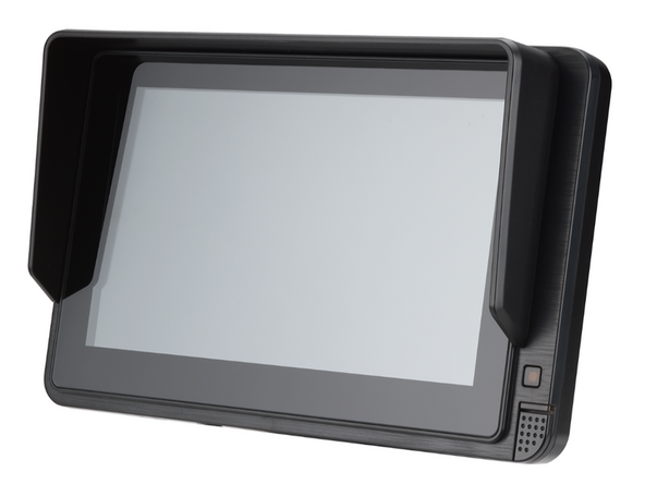
Introduction
The Zero-Latency Monitor enables GO Focus Pro to support up to 4 auxiliary cameras and provides a display output that functions as a blind-spot monitor. Auxiliary cameras connect to GO Focus Pro, appear as additional video channels, and the TVI output mirrors selected views for live in-cab display as a blind-spot monitor.
NOTE: Only available for use with TVI cameras, USB cameras are not supported.
Recommended Tools & Consumables
Hardware & Accessories
-
-
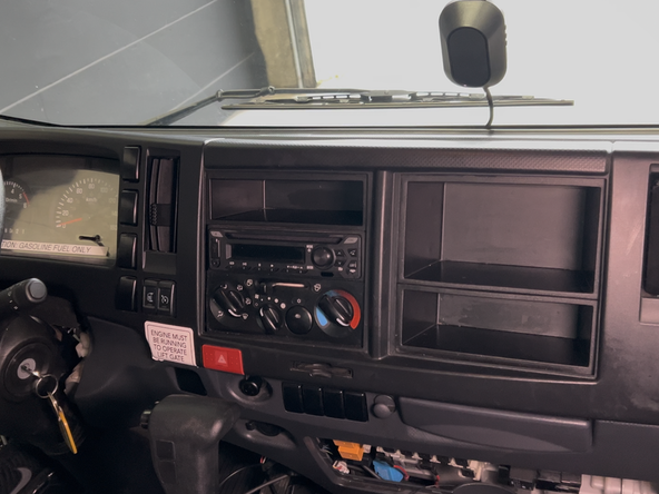
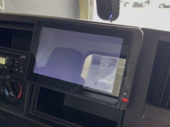
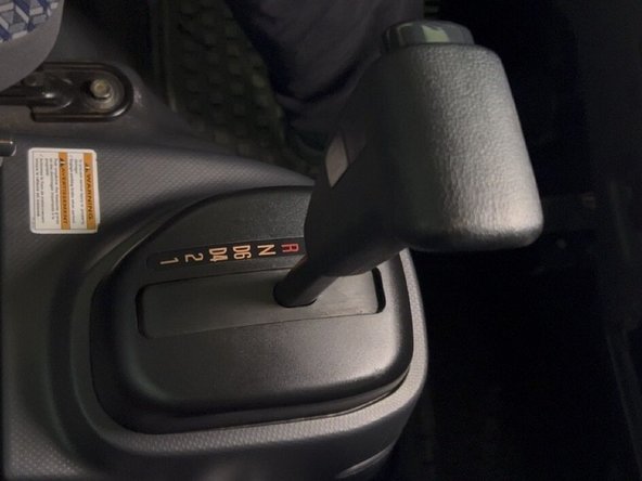
Determine the ideal mounting location for the monitor inside the vehicle cab.
-
For some vehicles, the monitor can mount into an available DIN slot in the dashboard.
-
Mounting locations may vary depending on the vehicle.
-
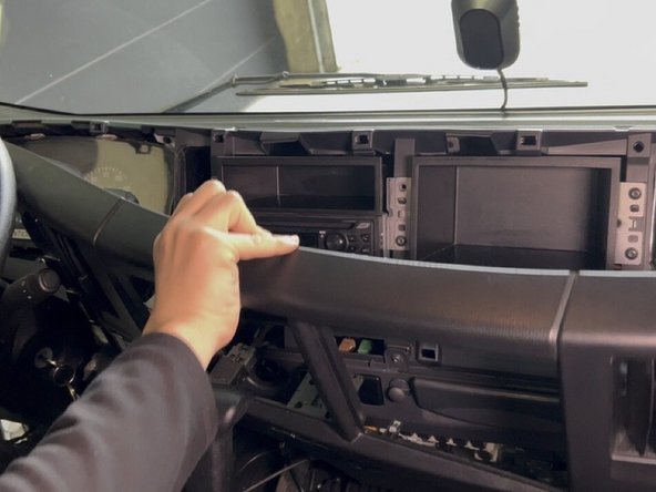
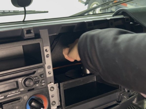
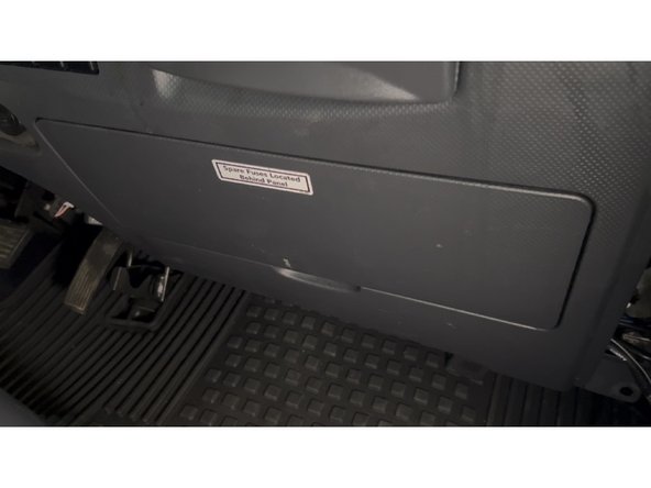
Remove any dash panels or trim pieces required to access the mounting location.
-
Use a trim removal tool or screwdriver to carefully unclip or unscrew the panels.
-
Set all removed panels and hardware aside in a safe location to be reinstalled later.
-
-
-
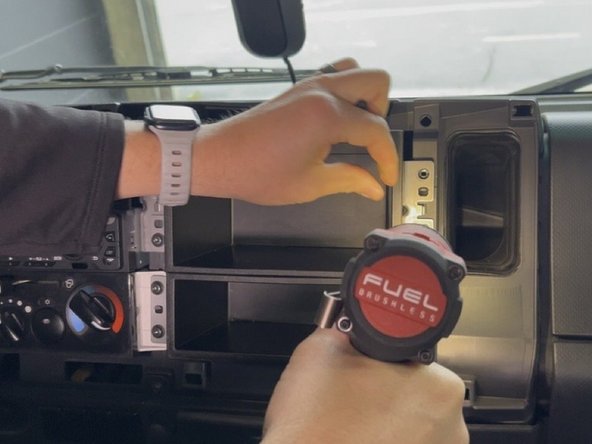
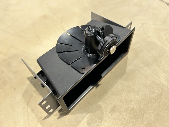
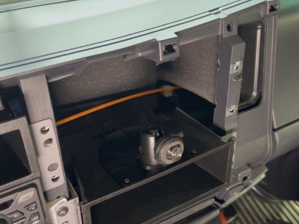
Install the mounting bracket assembly
-
Ensure to test fit the mounting bracket assembly and monitor before mounting to ensure the monitor does not obstruct any of the controls on the vehicle.
-
Secure the bracket using the provided hardware. Use a power drill to drive the mounting screws until the bracket is firmly seated.
-
The ball-mount arm on the bracket should be accessible from the front of the slot once installed.
-
Verify the bracket is secure and does not shift before proceeding.
-
-
-
Prepare the monitor harness for power connections using Geotab's best practices.
-
IMPORTANT: Check wire labels before connecting as the wire colors may vary.
-
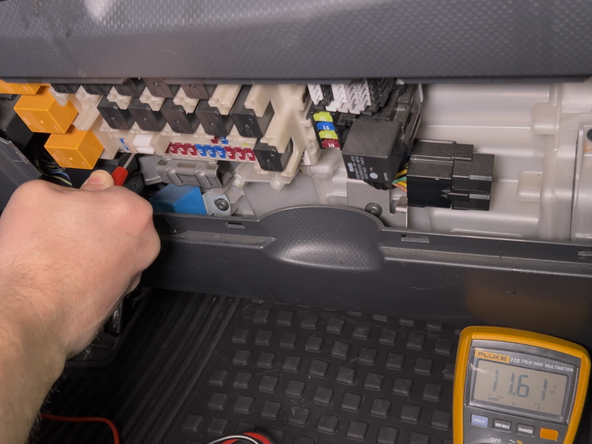
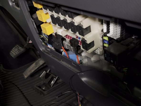
Connect the prepared harness to the vehicles fuse panel.
-
Always use a digital multimeter to locate and verify your connection points.
-
-
-
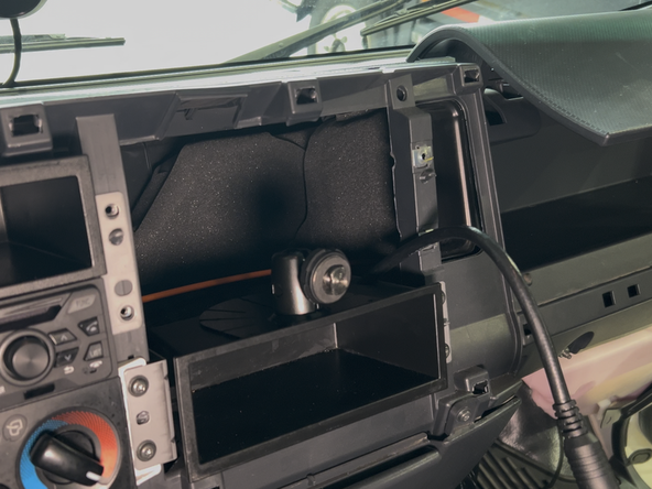
Route the monitor connector fom the vehicle fuse panel to the monitor mounting location.
-
Some vehicles may require you to drill a hole to pass the connector / cable through the dashboard.
-
Before drilling, check behind the mounting location to ensure the area is clear of any obstructions or electrical wires/components.
-
Ensure the cable is routed away from any moving parts, sharp edges, or pinch points.
-
Leave enough slack at the front to connect to the monitor once it is seated.
-
-
-
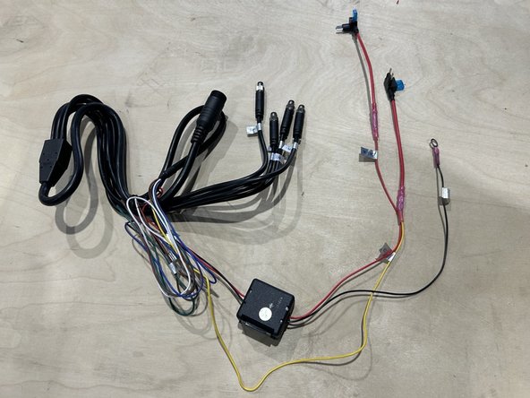
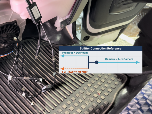
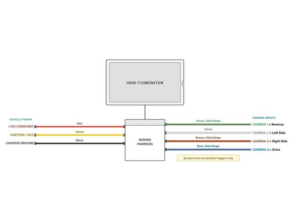
Connect the HRN-TVI-12-DISP Splitter Cable as shown in the image.
-
Each TVI camera will require a separate splitter Cable.
-
Both Splitter Cable outputs must be connected to the same input (for example, Cam 1) on both the TVI Monitor and Hub Cable.
-
Secure all excess wiring with cable ties.
-
Trim any excess cable tie.
-
-
-
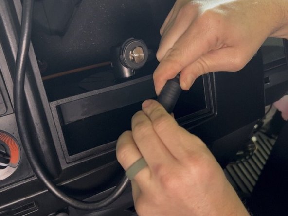
Connect the round connector from the harness to the monitor.
-
Carefully slide the monitor into the DIN bracket, engaging the ball-mount arm.
-
Adjust the monitor angle for optimal visibility from the driver seat, then tighten the ball-mount knob to lock the position.
-
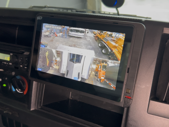
Turn on the vehicle's ignition and confirm the monitor powers on and displays a camera feed.
-
If the monitor does not power on, check all cable connections and verify the fuse is intact.
-
-
-
Monitor channel assignments.
-
Channel 1 - Rear Aux Camera (Dedicated to rear camera)
-
Channel 2 - Left Side Camera
-
Channel 3 - Right Side Camera
-
-
-
Locate the reverse trigger wire in the vehicle.
-
Route camera input wire to the location of the trigger wire in the vehicle.
-
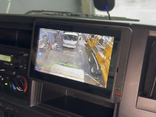
Channel 1 of the monitor should be used for reverse, this is the image that populates reverse lines when triggerd.
-
Connect the trigger wire to a 12V source that is active only when the vehicle is in reverse (e.g., reverse light power wire).
-
Shift the vehicle into reverse to confirm the rear camera view switches on automatically.
-
-
-
Ensure all excess wiring is secured using cable ties and that it does not obstruct the safe operation of the vehicle in any way.
-
Reinstall any dash panels or trim pieces that were removed.
-
Perform a final check of all camera views and monitor functions.
-