-
-
The primary reason for using a hydraulic sensor should be to detect activation of a hydraulic motor used on conveyors, augers or spinners.
-
For material application monitoring, use the component that “must” move for material to be applied. For instance, a typical manual spreader may have a conveyor to move material to a chute where it drops to a spinner. In this case, the conveyor is the function best monitored, as material cannot be applied without the conveyor moving.
-
Usually, a proximity sensor is better to monitor lift arms or plow position. Some exceptions do apply where a proximity sensor would be too difficult to mount, or subjected to excessive damage. Examples include belly plow, or wing plows on graders. Some clients may have a sensor preference, which will determine your telemetry capturing options.
-
Professional certified hydraulic installation is required. Attempting to perform these operations without proper training and knowledge can lead to injury or death. Please obtain professional installation services from trained technicians with welding and/or hydraulic certification.
-
-
-
It is the client’s responsibility to provide direction and support to ensure that the sensors are mounted in optimal locations that do not interfere with normal maintenance and operation.
-
Sensors should always be configured to be active when the equipment is being operated. An example would be when the manual spreader is actively applying material. This configuration helps reduce telemetry errors and maintains uniformity in winter operations reports.
-
-
-
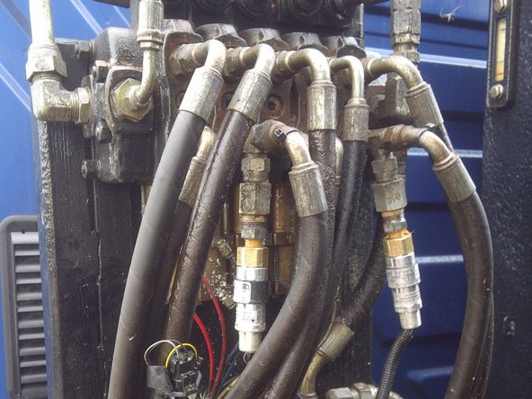
The hydraulic manifold is usually the best mounting location for hydraulic sensors. The sensor is closed when operation is active.
-
Never ground a sensor outside the cab. Always run both wires into the cab and protect the wires with loom.
-
-
-
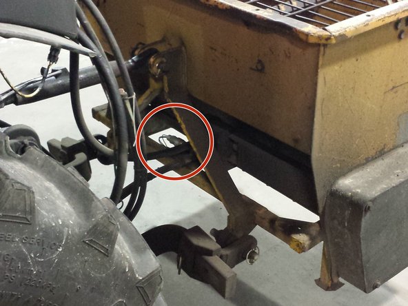
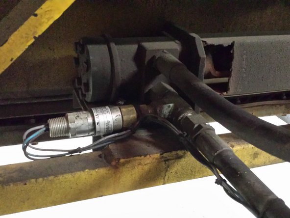
In some cases a hydraulic manifold may not be available and would require mounting the hydraulic sensor at either the piston or motor of the equipment being monitored.
-
Mounting the hydraulic sensor at the piston or motor exposes the sensor to a harsher environment with a higher likelihood of damage from impacts and/or corrosion. Additional measures may be required to protect the sensor from damage.
-
Never ground a sensor outside the cab. Always run both wires into the cab and protect the wires with loom.
-
-
-
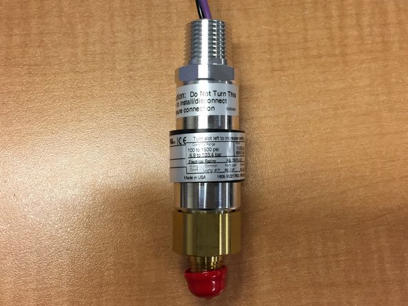
The sensor should provide a ground signal when the equipment is in its active state.
-
Violet - Common
-
Blue - Normally Open
-
Black - Normally Closed
-
-
-
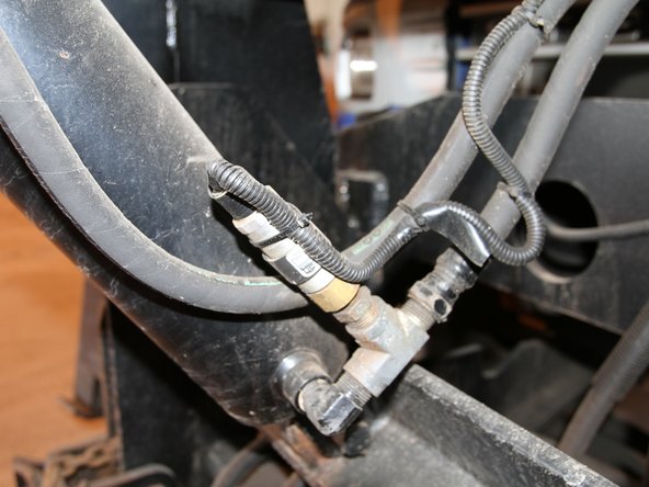
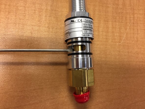
Slide the collar up to expose the adjustment shaft inside the hydraulic sensor.
-
Using a small flat blade screwdriver turn the shaft to increase or decrease the pressure setting at which the sensor will activate.
-
This sensor operates between 100 to 1500 psi.
-