
Introduction
Geotab® integrates with a wide selection of material spreader equipment to offer a complete winter solution.
The Geotab winter solution integrates with solid and liquid material controllers, temperature monitoring equipment, and telematic inputs. Telemetry data is sent through the GO device, and can be accessed in real-time, or via structured reports for operations management.
Professional installation
Installing the winter solution requires that the installer has sufficient technical knowledge and expertise with the GO device. In addition, the installer must have a Geotab Installer Certification and a Geotab Winter Solution certification.
Partner roles and responsibilities
| Reseller | The reseller is responsible for ordering the Winter Solution product and for providing a vehicle list with specific winter-related details for each vehicle: spreader make and model, temperature monitoring equipment (if any), plow sensor type and installed location, and any other required telemetry inputs. |
| Geotab | Geotab will ship the Winter Solution product to the Customer, and provide Winter Solution installation training, guides, and instructions. |
| Customer | The Customer must ensure that listed vehicles and winter solution products are available for installation. They must also weld sensor brackets and install hydraulic sensors as needed. |
| Installer | The installer is responsible for obtaining Winter Solution installation training and certification, installing the Winter Solution product according to Geotab standards. They are required to ensure the IOX-WRKS is configured for the spreader, and to verify spreader data and telemetry inputs. |
-
-
Correct input mapping for telemetry is crucial for winter installations. Failure to adhere to input mapping will result in erroneous data and winter reports will not function as intended.
-
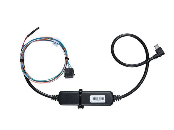
When installing only a GO Device with IOX-AUXM. Specifically, vehicles without automatic material spreaders that do not require the IOX-WRKS installation. Installation of a single IOX-AUXM will require the loop to be cut to obtain inputs AUX 5-8 for winter specific telemetries.
-
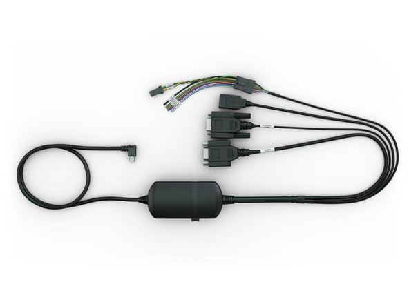
When installing the IOX-WRKS, inputs are pre-mapped to AUX 5 - AUX 8 respectively.
-
Additional telemetries using AUX 1-4 can be used for winter installations not listed in the input mapping. To configure the IOX-AUXM cable for inputs 1-4, DO NOT cut the loop. More information regarding the IOX-AUXM cable can be found here.
-
! IMPORTANT: To ensure an IOX accessory is recognized, it must be plugged into the GO device (or the IOX chain) before plugging in (powering up) the GO device.
-
-
-
When installing the IOX-WRKS, inputs are pre-mapped to AUX 5 - AUX 8 respectively.
-
IGN_BATT (+12V 650mA max) - provided ignition power for sensors
-
GND - provided ground for sensors
-
Do not connect IGN_BATT or GND to vehicle power or ground.
-
AUX 5 - Belly plow or Manual Spreader
-
AUX 6 - Front Plow
-
AUX 7 - Wing Plow
-
AUX 8 - Tow Plow or Beacon
-
-
-
When used in collaboration with the IOX-WRKS to obtain 4 additional telemetries. DO NOT cut the loop. This will maintain it's AUX 1-4 configuration.
-
When used for winter telemetry where an IOX-WRKS in not required, the loop must be cut to maintain winter input mapping AUX 5-8.
-
-
-
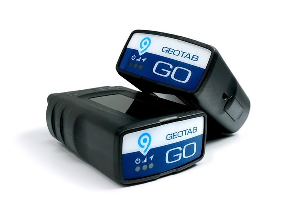
GO device installations for the Winter Solution involve a GO device and a T-harness. Refer to the HRN-GS16K22 Standard 16-Pin T-Harness Kit & HRN-GS09K2 Universal Heavy Duty T-Harness Kit guides for installation instructions.
-
However, note that some installations (such as purpose-built or adapted yellow iron) require the use of a GO Rugged with a 3-wire harness (HRN-RW03S4). Such vehicles may also require different mounting locations.
-
-
-
Any IOX installations or hardware integrations must be done prior to connecting the GO device to the vehicle ECM port. To ensure that the installation is efficient and organized, and to keep cable extensions down to a minimum, the installer should consider the location of all required telemetry inputs and material spreader ports before installing.
-
✱ NOTE: The IOX-WRKS is only compatible with GO9 / GR9 and newer devices.
-
More information regarding the IOX-WRKS cable can be found here.
-
-
-
Mounting sensors typically involves welding or hydraulics. Attempting to perform these operations without proper training and knowledge can lead to injury or death. Please obtain professional installation services from trained technicians with welding and/or hydraulic certification.
-
It is the client’s responsibility to provide direction and support to ensure that the sensors are mounted in optimal locations that do not interfere with normal maintenance and operation. It is advisable to always mount proximity sensors perpendicular to the moving equipment so that the sensor does not get impacted or damaged.
-
Sensors should always be configured to be active when the equipment is being operated. An example would be active when the plow is down, or when the manual spreader is actively applying material. This configuration helps reduce telemetry errors and maintains uniformity in winter operations reports.
-
For the associated documents, refer to the Sensors category.
-
-
-
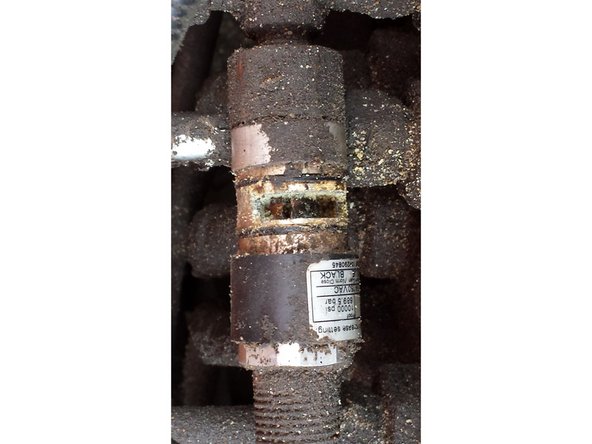
Winter vehicles operate in a highly corrosive environment. Use the following guidelines to reduce corrosion.
-
All wiring connections whether in-cab or external should be soldered and protected with heat shrink or tape.
-
All external wiring connections must be protected from corrosion, placed in wire loom, and dielectric grease used on all weather exposed mated connections. (eg. proximity sensors / cables, or where a connector is used)
-
Dielectric grease must be applied to all proximity sensor connectors, both internally and externally.
-
-
-
While there are many manufacturers and suppliers of material spreaders, all are designed to apply various materials (brine, salt, sand) to the road surface to improve drivability. This is usually done via Pulse Width Modulation (PWM) control of the hydraulic valves.
-
When interfacing with these controllers, it is important to use the correct software configuration, controller firmware, and cabling. Some controllers require specific settings or port configurations beyond any firmware updates. Also, to confirm data flow, some controllers require a specific event change, or for simulation mode* to be activated.
-
Automatic spreaders are those where a data integration is available in which case the IOX-WRKS is used for this integration. For a manual spreader; one without data integration availability, material usage is captured using a hydraulic sensor on the auger or conveyor.
-
✱ NOTE: Simulation mode, or SIM, is a manual setting where the operator can instruct the spreader to bypass the ground speed sensor. This allows for the spreader to be operated and material dispensed without moving the vehicle. SIM mode can be used to verify data to ensure the IOX-WRKS is properly capturing spreader data.
-
While in SIM mode (manual mode), material totals are not captured. This is an intentional design feature by the spreader manufacturers.
-
For the associated documents, refer to the Controllers category.
-


Team

Authors: Field Service Install Member of Authors: Field Service Install
3 Members
66 Guides authored