
Introduction
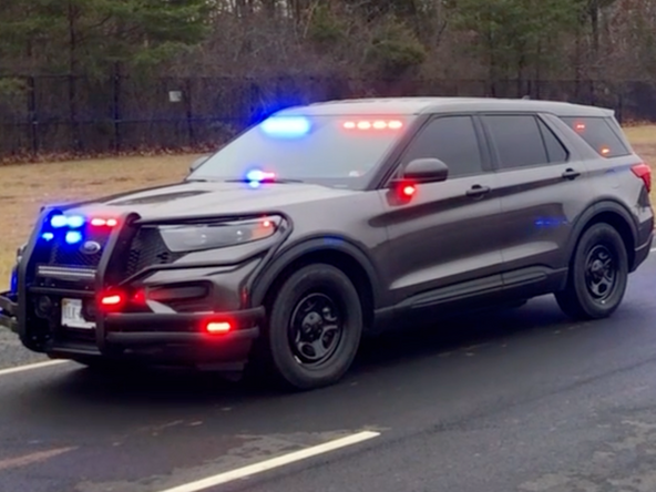
The Geotab® Emergency Vehicle Solution uses the IOX-AUXM to integrate with emergency lights, sirens, and additional telematic inputs to offer a complete solution for Police Vehicles, Ambulances, and Fire Trucks.
Telemetry data is sent through the GO device, and can be accessed in real-time, or via structured reports for operations management.
Professional installation
Installing the Emergency Vehicle Solution requires that the installer has sufficient technical knowledge and expertise with the GO device. In addition, the installer must have completed the installer certification courses required for this solution.
Partner roles and responsibilities
| Partner | The partner is responsible for ordering the Emergency Vehicle Solution product and for providing a vehicle list with specific telematic input details for each vehicle: vehicle type, lights and siren make and model (controller), and any other required telemetry inputs. |
| Geotab | Geotab will ship the Emergency Vehicle Solution product to the Customer, and provide Emergency Vehicle Solution installation training, guides, and instructions. |
| Customer | The Customer must ensure that listed vehicles and Emergency Vehicle Solution products are available for installation. They may also be required to provide wiring diagrams / schematics for lights and siren controllers if needed. |
| Installer | The installer is responsible for obtaining Emergency Vehicle Solution installation training and certification, installing the Emergency Vehicle Solution product according to Geotab standards. They are required to ensure the telemetry inputs are connected according to the Input Mapping table as specified by Geotab. |
Input Mapping
| Input | Color | Emergency Vehicle * |
| IOX-AUXM | ||
| AUX1 | Blue | Panic |
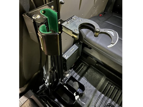
| AUX2 | Orange | Gun Lock |
| AUX3 | Green | Primary Lights ** |
| AUX4 | White | Siren |
| * Emergency (First Response) vehicles may include: Police, Fire, Paramedic, By-law or other first response vehicles. | ||
| ** Primary Lights refer to flashing lights used when responding to an Emergency. | ||
-
-
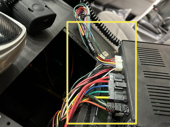
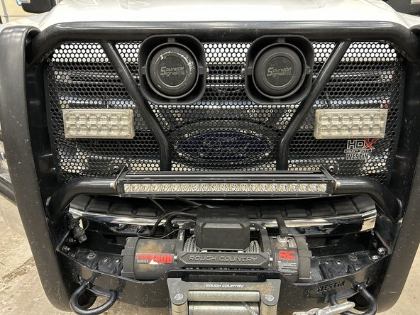
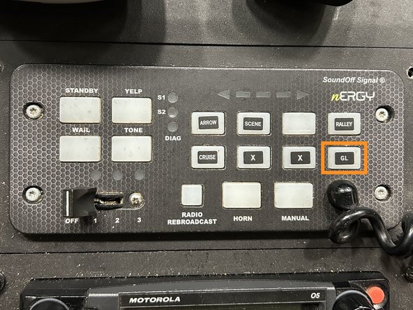
Emergency vehicles will have a controller to activate the emergency lights and siren located within easy reach of the driver.
-
You may also find additional telemetry inputs available through the control panel such as Gun Lock and Panic.
-
-
-
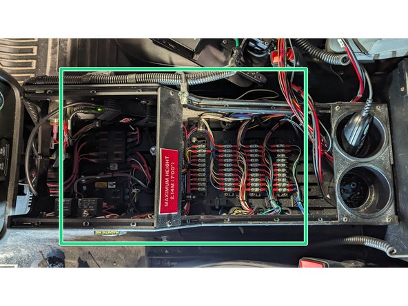
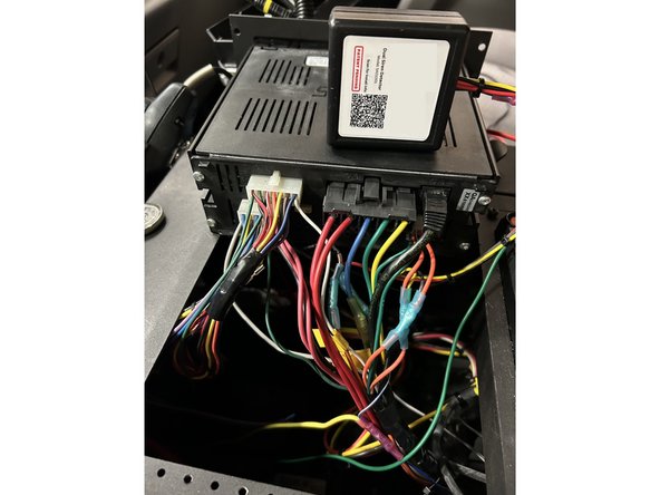
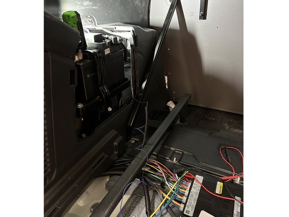
Some controllers use CANBUS to communicate with a control module located in a separate location in the vehicle.
-
CANBUS controllers can be identified by looking at the back of the control panel. RJ45 connectors indicate a CANBUS system.
-
You may need to remove dash panels, storage boxes and/or other items to access the control module depending on its location within the vehicle.
-
The customer / vehicle up-fitter may be able to provide guidance on the location of the control module.
-
-
-
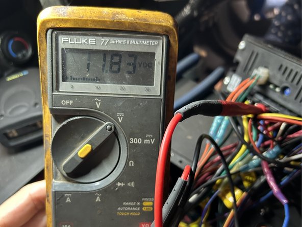
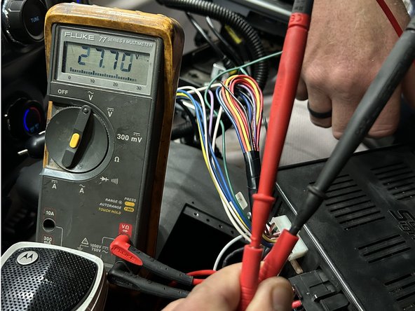
Locate and test the wire that shows 12V DC when the primary lights are activated using a multimeter.
-
AUX 3 - Primary Lights
-
-
-
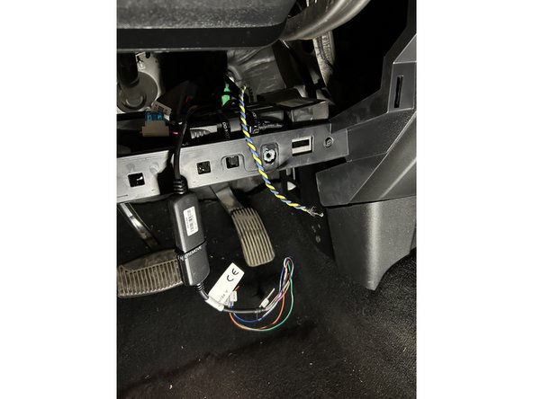
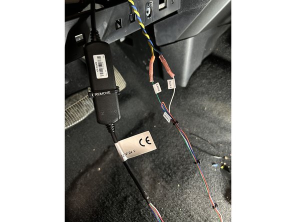
Locate and test the wires that show 0-36V AC when the siren is activated using a multimeter.
-
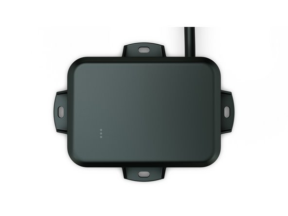
A Siren Detector module will be required to convert the AC signal from the siren wires to a 12V DC output.
-
Ensure to following the wiring instructions provided by the manufacturer of the Siren Detector module.
-
AUX 4 - 12V DC output wire from the Siren Detector Module.
-
-
-
Locate and test the wire that shows 12V DC when the gun lock is activated using a multimeter.
-
AUX 2 - Gun Lock
-
-
-
You may need to run wires from the control module of the Emergency Vehicle Controller to the IOX-AUXM.
-
Ensure to avoid any pinch points and sharp corners when running wires. Use wire loom where necessary.
-
All connections should be made by either soldering and sealing, or using heat shrinkable butt connectors.
-
Use cables ties to secure all excess wiring.
-
-
-
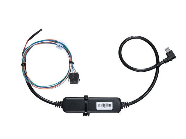
To configure the IOX-AUXM cable for inputs 1-4, DO NOT cut the loop. More information regarding the IOX-AUXM cable can be found here.
-
! IMPORTANT: To ensure an IOX accessory is recognized, it must be plugged into the GO device (or the IOX chain) before plugging in (powering up) the GO device.
-
Correct input mapping for telemetry is crucial for Emergency Vehicle installations. Failure to adhere to input mapping will result in erroneous data.
-
-
-
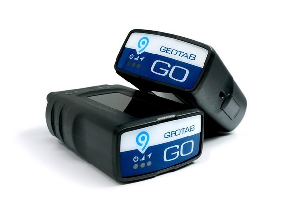
GO device installations for the Emergency Vehicle Solution involve a GO device and a T-harness. Refer to the HRN-GS16K22 Standard 16-Pin T-Harness Kit & HRN-GS09K2 Universal Heavy Duty T-Harness Kit guides for installation instructions.
-
However, note that some installations such as purpose-built or small battery vehicles (ATV's / Motorcycles) require the use of a GO Rugged with a 3-wire harness (HRN-RW03S4). Such vehicles may also require different mounting locations.
-


Team

Authors: Field Service Install Member of Authors: Field Service Install
3 Members
66 Guides authored