Recommended Tools & Consumables
Hardware & Accessories
-
-
NOTE: Professional Installation Required — Installation of the ORBCOMM Asset Tracker requires the installer to have sufficient technical knowledge and expertise for mobile device installation and integration into modern vehicles/assets
-
Some installations are not straight forward and must be completed by an Authorized Installer to ensure a secure installation.
-
An unsecure device installation can cause poor electric and/or data connection that can lead to short circuits and fires or cause malfunctions.
-
-
-
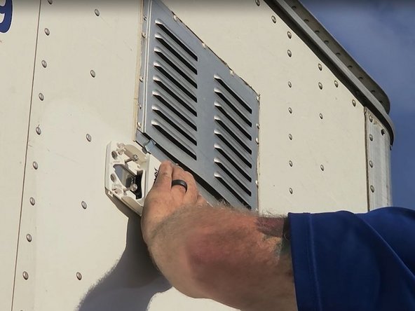
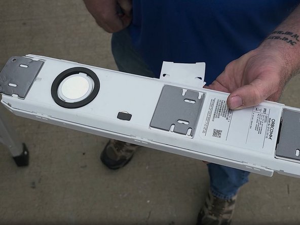
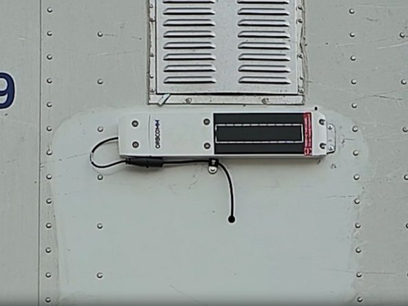
Find a suitable location on the trailer to mount the device.
-
To reduce likelihood of vandalism, mount the device as high as possible above the nose box. Use your ladder.
-
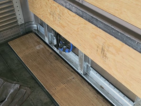
Before drilling any holes, verify that there are no obstructions inside the trailer, make sure you have access to the interior panel, and obtain approval from the Fleet Manager.
-
-
-
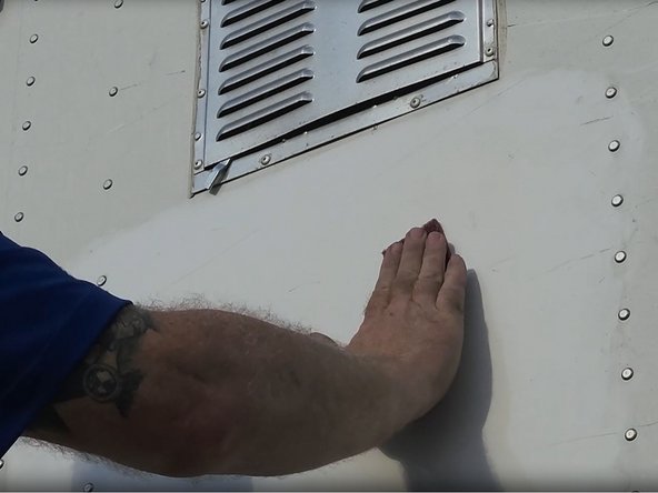
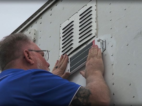
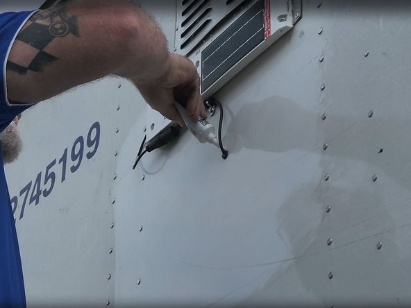
Use the provided alcohol pad to clean any dirt or grease from the mounting area on the asset, and then use the scour pad. DO NOT scour beyond the the asset tracker's mounting area.
-
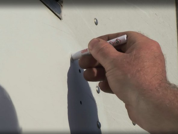
Next, clean the points using the alcohol pads and then prime the points using the 3M adhesive primer.
-
Make sure that the primer is dry before mounting the device!
-
-
-
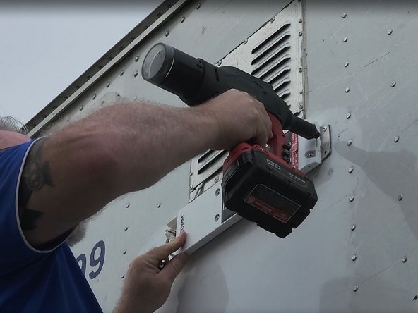
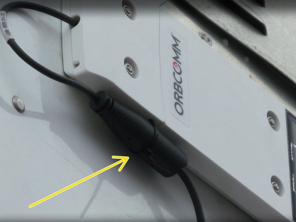
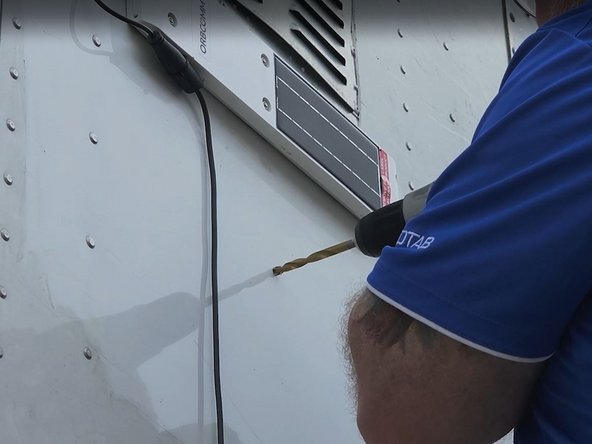
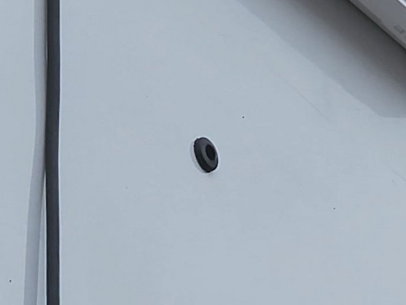
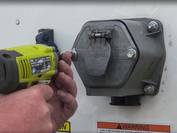
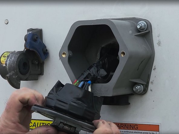
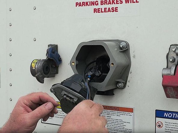
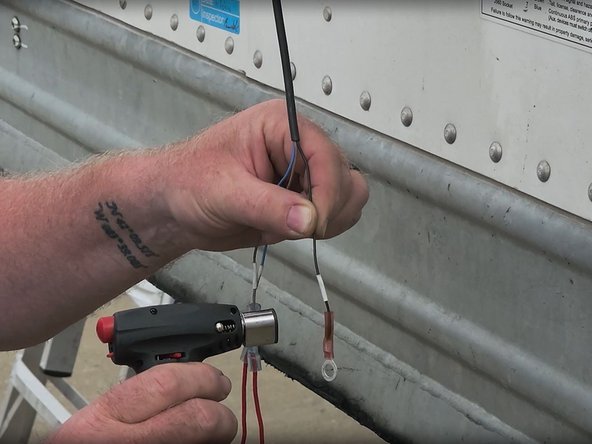
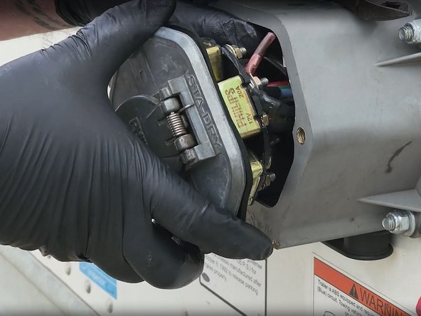
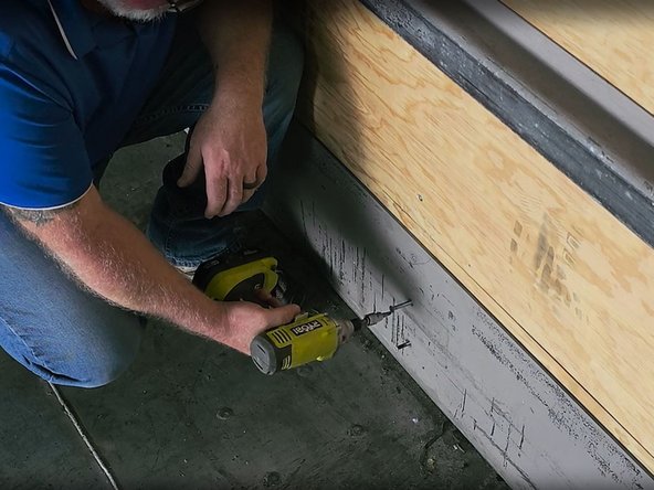
Drill a hole for the harness to pass through and install a grommet in the hole.
-
A hole location directly in line with the nose box makes for easier routing and may even be retrievable from the nose box without removing the interior access panel.
-
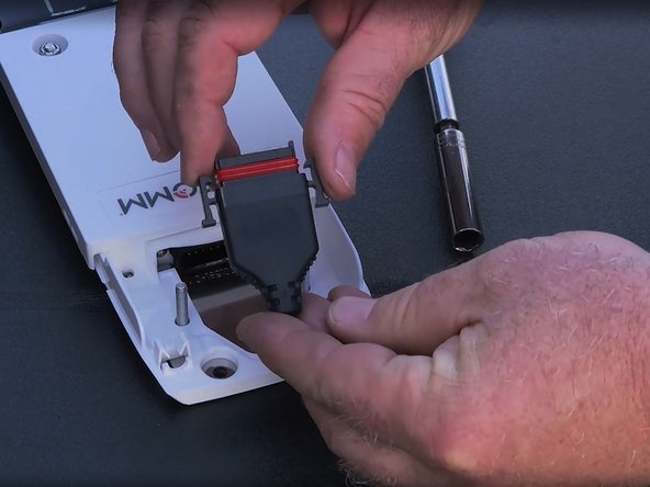
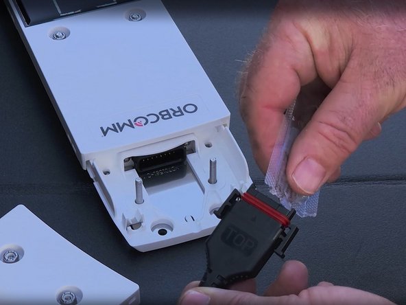
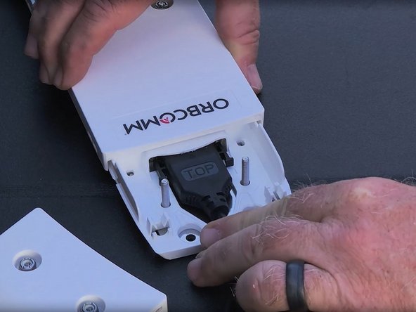
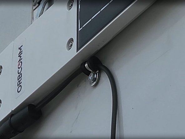
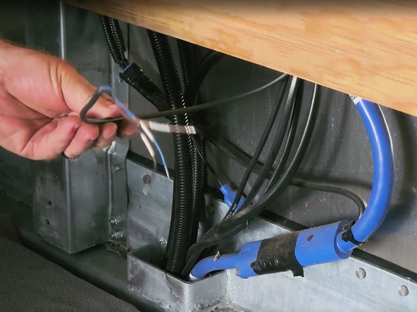
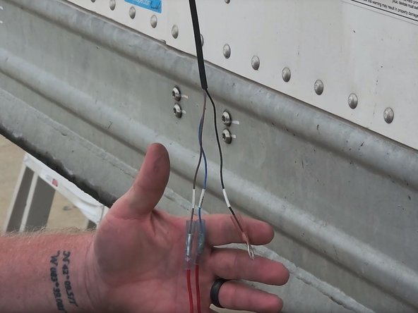
Align the harness with the passthrough hole and secure it using the included P-clamps and screws.
-