Introduction
Installation Best Practices
Input Mapping
When installing the IOX-AUXM for telemetry inputs, it is mandatory that you adhere to a consistent input mapping strategy within a fleet. Having vehicles with different input mapping can impact the customer’s ability to capture and process data. Refer to the table below for Geotab recommendations.
✱ NOTE: It is mandatory to follow the input mapping described in the table below.
✱ NOTE: During installation, when an input is triggered, the device will beep the same number of times as the input/AUX number. For example, AUX1 beeps once, AUX3 beeps three times, AUX5 beeps five times, and so on.
✱ NOTE: To facilitate learning consistency between vehicles, IOX-AUXM learning must always start from the off (no operations) position.
✱ NOTE: If self-learning does not initiate, and/or no beeps are heard when AUX states are changed do the following:
- While keeping IOX-AUXM connected to the GO device, unplug the G0 device from the vehicle for approximately 1 minute.
- Reinstall device to vehicle connection.
- When you hear the initial 6 beeps, unplug the GO device again.
- Reinstall device to vehicle connection.
- Retest self learn routine.
| Input | Color | Hi-rail | School Bus | Security | Public Works | Emergency Vehicles* | Winter Solution | Telecom / Utility |
|---|---|---|---|---|---|---|---|---|
| IOX-AUXM #1 | ||||||||
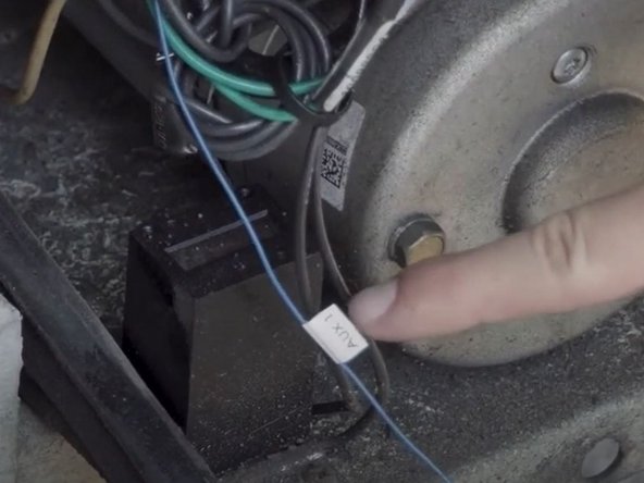
| AUX1 | Blue | PTO (Power Take-Off) | Overhead Red warning lights | Door lock | LH Gutter broom | Primary Lights** | Beacon*** | |
| AUX2 | Orange | Hi-rail | Overhead Amber warning lights | Panic | RH Gutter broom | Secondary Lights | Boom / Bucket | |
| AUX3 | Green | Crane | Door open | Dump box up | Panic / Gun Lock | Outrigger | ||
| AUX4 | White | Compressor | Lift door open | PTO | Siren | PTO / AUX Engine | ||
| IOX-AUXM #2 | ||||||||
| AUX5 | Blue | Generator | Belly plow or manual spreader | |||||
| AUX6 | Orange | Welder | Front plow | |||||
| AUX7 | Green | Tool circuit | Wing plow | |||||
| AUX8 | White | Panic | Tow plow or beacon*** | |||||
| * Emergency (First Response) vehicles may include: Police, Fire, Paramedic, By-law or other first response vehicles. ** Primary Lights refer to flashing lights used when responding to an Emergency. *** Beacon refers to rotating or flashing work light on the vehicle. | ||||||||
Expanding your IOX-AUXM
The IOX-AUXM can expand from four to eight auxiliaries by plugging in a second IOX-AUXM to the expansion port of the first and following the steps below.
✱ NOTE: You must remove the cable tie from the original IOX-AUXM.
To have the second connected IOX-AUXM report as AUX 5-8, do the following:
- Locate the red and black loop, also known as Short.
- Cut the wires to configure the IOX-AUXM to act as Aux 5-8.
- Secure both IOX-AUXMs with a cable tie.
Self-Learning Logic
The IOX-AUXM uses a learning algorithm to determine the circuit type — listed below — to which the IOX-AUXM is connected:
- Ground-High Circuit — The auxiliary is connected to ground when the switch is in one position, and high voltage (i.e. 12 V) when the switch is in the other position.
- Ground-Float Circuit — The auxiliary is connected to ground when the switch is in one position, and there is an open circuit when the switch is in the other position.
- Float-High Circuit — The auxiliary is connected to high voltage when the switch is in one position, and there is an open circuit when the switch is in the other position
Connecting Additional IOXs to an IOX-AUXM
When connecting additional IOX devices to an IOX-AUXM, ensure the USB connector is seated correctly and secure the connection with a cable tie.
✱ NOTE: While up to 5 IOX devices can be daisy chained, the number of IOX-AUXMs specifically is limited to 2.
Termination Shunt
The IOX comes with a termination shunt installed in the expansion port. If you plan to install more than one IOX in a daisy chain, you must remove the shunt from each device in the line.
The shunt must remain in the last IOX and be secured with a cable tie, which ensures that the GO device detects and configures the IOX as effectively as possible.
For GO6 devices, up to 4 IOXs can be daisy chained.
For GO7 and newer devices, up to 5 IOXs can be daisy chained.
Recommended Tools & Consumables
-
-
Before starting the installation, ensure the Geotab GO device is unplugged from the vehicle.
-
-
-
Connect the desired auxiliaries in the vehicle to the IOX-AUXM wires, as needed.
-
The IOX-AUXM can expand from four to eight auxiliaries by plugging in a second IOX-AUXM to the expansion port of the first and following the steps described in the introduction.
-
When the loop is cut, the second IOX-AUXM will always report as AUX 5-8, regardless of whether an AUX 1-4 is installed. The loop must be cut before connecting the IOX to the chain.
-
-
-
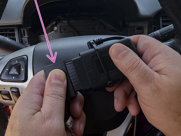
Remove the rubber cover on the GO device to expose the IOX port.
-
Plug the IOX cable into the GO device.
-
Important: you must plug IOX devices into the GO device BEFORE powering up the GO device.
-
-
-
Turn on the vehicle ignition.
-
Verify the LED pattern.
-
The device emits 2 quick beeps every 60 seconds during setup. When setup is complete, all three LEDs turn solid and the device emits 10 quick beeps.
-
-
-
Route the device and harness to the mounting location as needed. The mounting location should have as clear a line of sight to the sky as possible (for cellular/GPS connectivity). Lines of sight through plastics, glass, and composites are generally acceptable.
-
Ensure cable does not interfere with any moving parts.
-
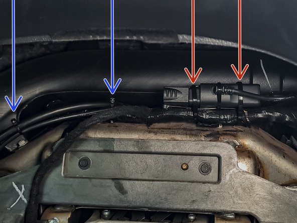
Secure harness as needed with cable ties.
-
Secure the device using 2 cable ties.
-
To ensure reporting quality, the device must be secured with no free movement!
-
Device must NOT be secured such that the bottom side is in direct contact with metal!
-
-
-
All in-vehicle devices and related cabling must be securely fastened and kept clear of all vehicle controls, airbags, and gas, brake and clutch pedals.
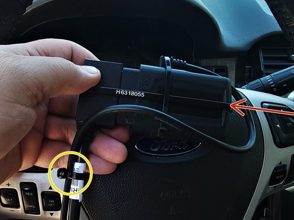
-
This requires the use of a cable tie when securing the device or any extension harness to the OBD connector, securing both sides of the harness. If you do not use a cable tie, vibration in the vehicle can lead to a loose connection which could cause the vehicle’s engine computer to fail, causing potential loss of vehicle control and serious injury.
-
Inspect devices and cabling regularly to ensure all devices and cabling continue to be securely attached.
-
If at any point after an in-vehicle device is installed a warning light illuminates on the vehicle dash or the vehicle stalls or has a marked drop in performance, shut off the engine, remove the device, and contact your reseller. Continuing to operate a vehicle with these symptoms can cause loss of vehicle control, and serious injury.
-
-
-
Navigate to one of the following:
-
-
-
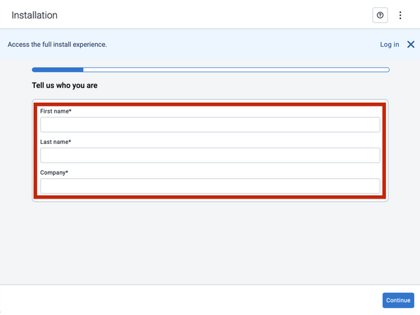
Note that the following steps are for the public version of MyInstall.
-
If you have an installer MyAdmin account, use this link
-
This link is also accessible via the MyInstall Public page.
-
-
-
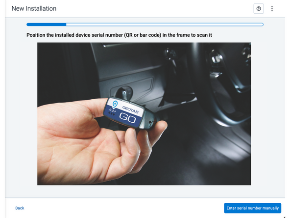
Two options are available to enter the device serial number:
-
Scan the device serial number (QR or barcode) using your mobile device.
-
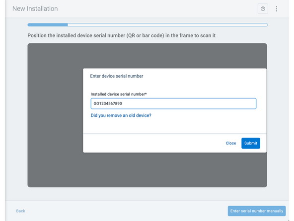
Press Enter serial number manually, enter the serial number, and then press Submit.
-
If you are also removing an old device, press Did you remove an old device? and then enter the removed device serial number.
-
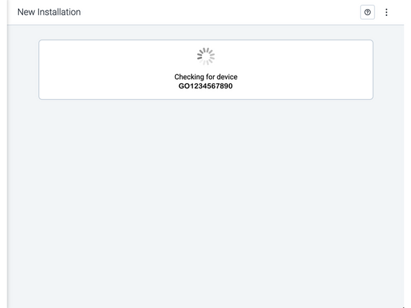
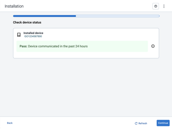
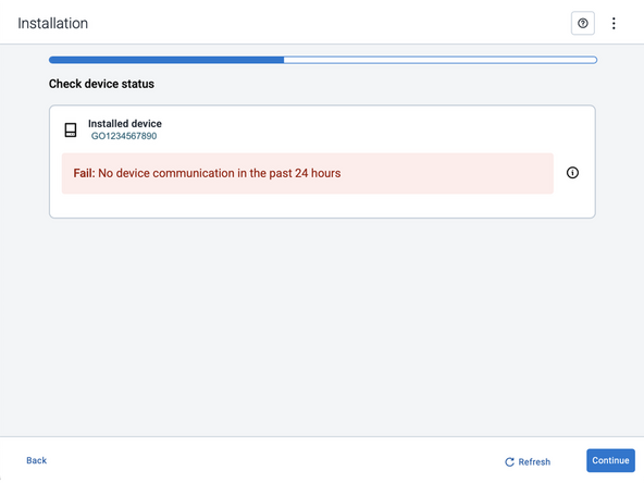
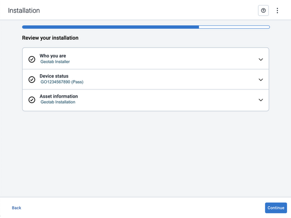
MyInstall takes a moment to check the device status.
-
-
-
Installed device
-
Pass – The device has successfully communicated with the network in the last 24 hours.
-
Fail – The device has not communicated with the network in the last 24 hours.
-
If the device status shows as FAILED, verify the LED status and turn the ignition / engine off and on again.
-
Press Refresh to check the status again.
-
Refer to the MyInstall User Guide for detailed instructions.
-
-
-
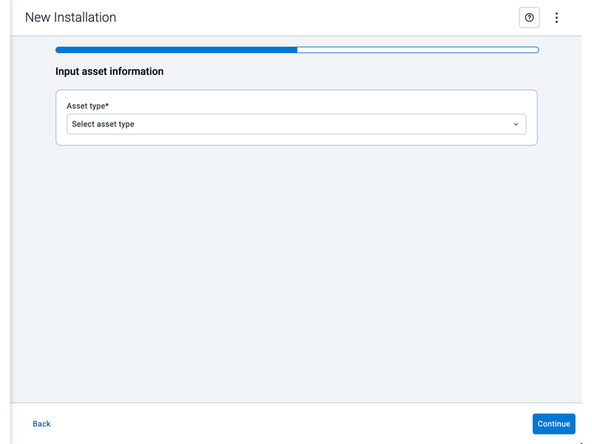
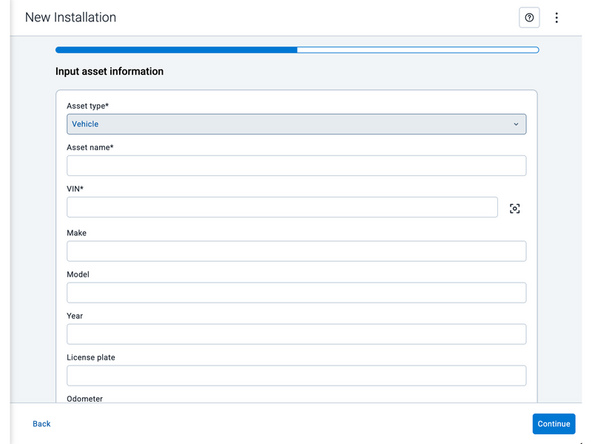
Asset name — Enter the vehicle or asset name. This field is mandatory.
-
VIN — Scan or enter the vehicle identification number (VIN). For scanning, select the scan icon [O] beside the field. This field is mandatory.
-
Make, Model, and Year — This information will be auto populated when you scan or enter a valid VIN. If it is not autopopulated, enter the information manually. NOTE: For some vehicle makes and models, the autopopulate option might not be possible.
-
License plate — Enter the vehicle license plate.
-
Odometer — Enter the vehicle odometer, and select the measurement unit (km or miles).
-
Engine hours — Enter the vehicle engine hours.
-
Camera ID (GO device only) — Scan or enter the installed camera identification (ID) number. NOTE: Depending on the camera type, the camera ID number can also be the camera’s International Mobile Equipment Identity (IMEI), or serial number. Select the information icon ⓘ to learn more about your camera’s ID number.
-
Work order reference — If applicable, enter a work reference number that is associated with the installation.
-
-
-
For the latest version of the Limitations of Use
-
Your in-vehicle devices must be kept clear of debris, water and other environmental contaminants. Failure to do so may result in units malfunctioning or short-circuiting, which can lead to a fire hazard and cause loss or serious injury.
-
This product does not contain any user-serviceable parts. Configuration, servicing, and repairs must only be made by an authorized reseller or installer. Unauthorized servicing of these products will void your product warranty.
-
The simplified EU declaration of conformity referred to in Article 10(9) shall be provided as follows:
-
Hereby, Geotab (Address: 2440 Winston Park Drive, Oakville, Ontario L6H 7V2, Canada, Phone number: 1 (877) 436-8221) declares that the radio equipment type ‘telematics device’ is in compliance with Directive 2014/53/EU. The full text of the EU declaration of conformity is available here.
-
WARNING: Cancer and Reproductive Harm
-