Introduction
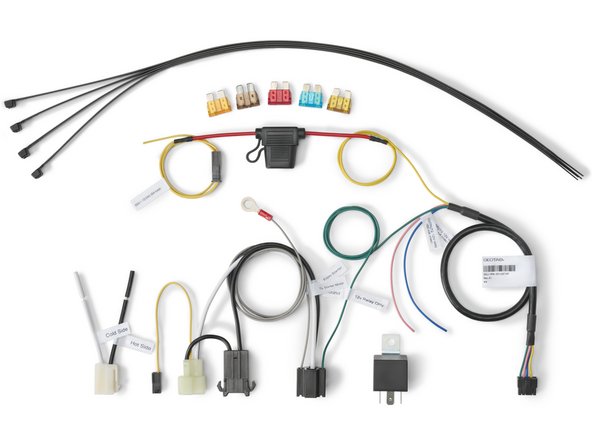
Installation instructions for the IOX-KEYLESS solution with SID (Starter Inhibit Device) using the HRN-SIFUSETAP harness.
Recommended Tools & Consumables
-
-
WARNING! Some installations are not straightforward and must be completed by an Authorized Installer to ensure a secure installation.
-
An unsecure device can result in poor electric and/or data connections, which can lead to short circuits and fires or cause malfunctions of vehicle controls that can result in serious personal injury or significant damage to the vehicle. Some examples requiring professional installation from an Authorized Installer are:
-
The OBD port location is such that the device protrudes and interferes with entering or exiting the vehicle, or located where it could be inadvertently kicked or bumped during vehicle operation.
-
The device isn't fully secured and so may come loose with vibrations or accidental contact.
-
An electrical harness or additional wiring is required.
-
Vehicle mounting modifications are required to secure the device, i.e. removing of panels; deformed/damaged OBD connector; or physical damage to the electrical wiring.
-
The device does not power on and beep six times when first installed.
-
The installer questions their ability to complete a secure installation according to these instructions.
-
-
-
WARNING! Do not attempt to install, reconfigure, or remove any product from a vehicle while the vehicle is in motion or otherwise in operation. All installation, configuration, or removal must be done only in stationary vehicles which are securely parked.
-
Attempting to service devices while the vehicle is in motion could result in malfunctions or collisions, leading to death or serious personal injury.
-
-
-
WARNING! Installation of this product into vehicle systems requires professional installation by a qualified technician who is thoroughly familiar with any circuits involved.
-
Installing the Geotab SID solution requires real-time access to the host vehicle wire interface diagrams for starter control (i.e. ALLDATA™, WireSheet™, Mitchell1 ProDemand™ / eAutoRepair™ or equivalent). Typically, the diagrams are provided to car security solution installers.
-
-
-
WARNING! The Geotab SID solution must not be installed in such a manner where it has the potential to disable propulsion and/or prevent vehicle control while the vehicle is in motion.
-
Never install a circuit interrupt on any circuit that may interfere with the safe operation of a vehicle or cause the engine to stop while the vehicle is in motion — such as fuel lines, brake switch, or multiplexed circuits.
-
Some vehicles stop the engine every time the vehicle comes to a stop, and automatically restarts the engine upon pressing the accelerator pedal.
-
Installers in these vehicles need to ensure activation of the Starter Inhibit feature does not disable the vehicle in a precarious location (i.e. a busy intersection) and does not leave the vehicle unable to move to a safe location or other direct or indirect effects resulting from the installation of the Starter Inhibit feature.
-
-
-
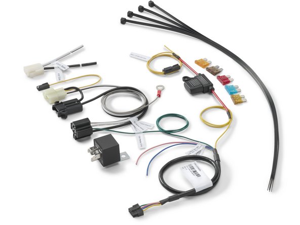
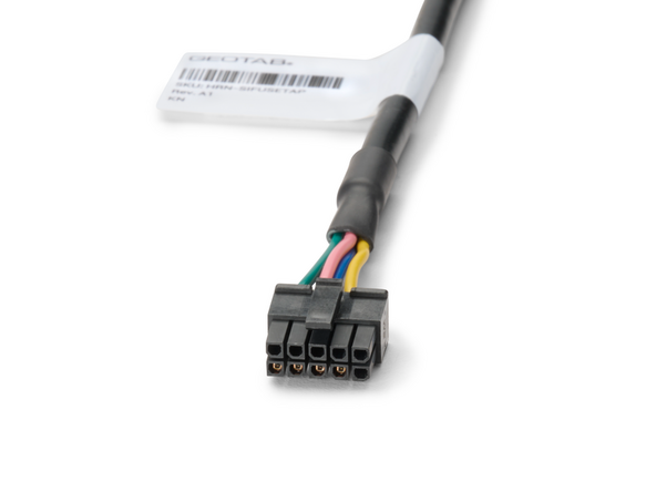
This installation guide covers the installation of the HRN-SIFUSETAP - Starter Inhibit Harness for IOX-KEYLESS.
-
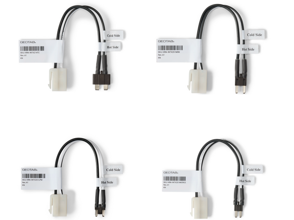
The following fuse interrupters are available to use with the HRN-SIFUSETAP harness to interrupt a circuit in the vehicles fuse panel:
-
HRN-INTX21ATC - ATC Fuse Interrupter
-
HRN-INTX2S1MINI - Mini Fuse Interrupter
-
HRN-INTX2S1LPM - LP Mini Fuse Interrupter
-
HRN-INTX2S1MICRO2 - Micro2 Fuse Interrupter
-
-
-
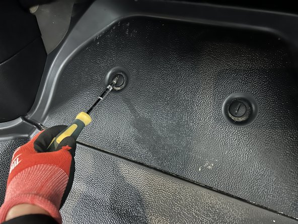
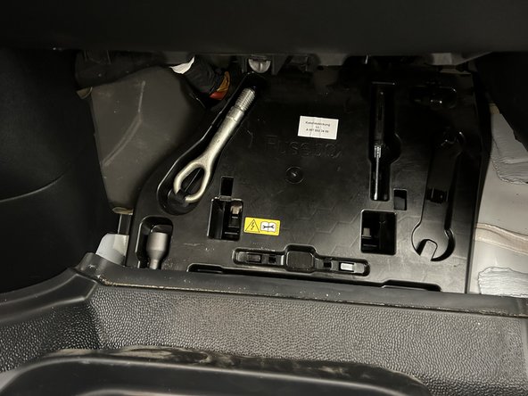
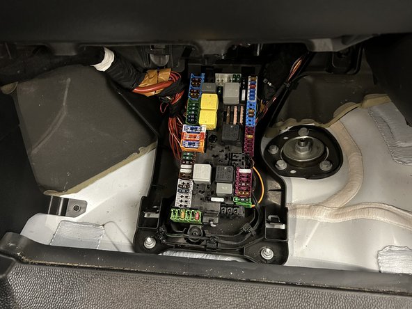
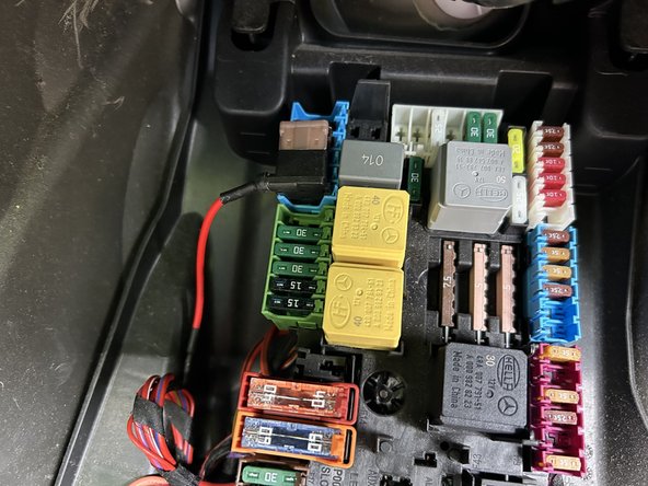
Locate and access the vehicles fuse panel.
-
Some vehicles may require you to remove dash panels / covers to access the fuse panel.
-
-
-
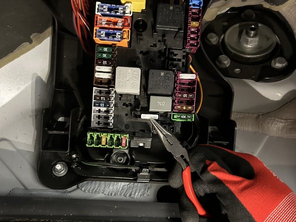
Locate and test the fuse for Starter Interrupt using a Digital Multimeter.
-
Ensure the fuse does not interfere with safe operation of the vehicle and does not cause an permanent fault codes to be displayed on the vehicle dashboard.
-
The fuse used for Starter Interrupt should prevent the vehicle from starting when the engine is off.
-
The engine should remain running if the fuse is disconnected from the vehicle while the engine is running.
-
It is highly recommended to refer to vehicle wire interface diagrams for starter control (i.e. ALLDATA™, WireSheet™, Mitchell1 ProDemand™ / eAutoRepair™ or equivalent) to locate the starter wire in the vehicle.
-
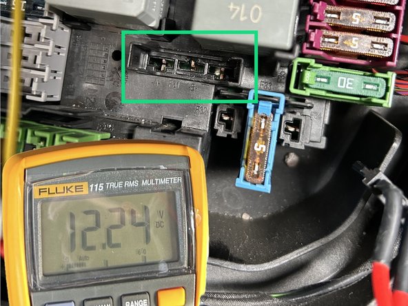
Remove the fuse and verify the HOT side of the fuse slot with a digital multimeter.
-
When testing the HOT side of fuse slot, also check to see if the fuse is a Constant 12V/24V or a Switched Ignition circuit.
-
-
-
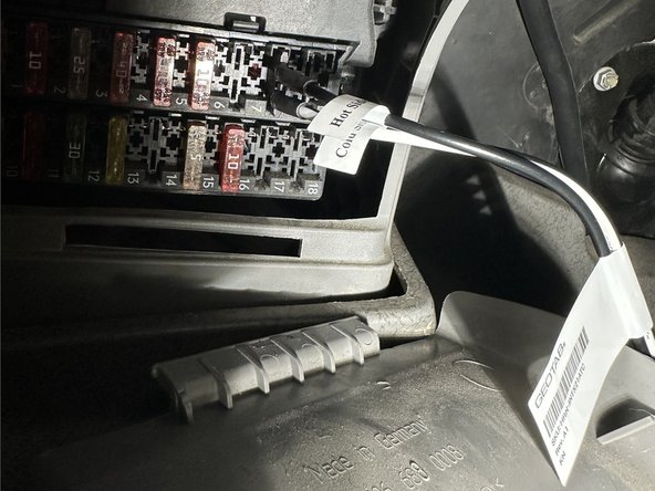
Insert the Fuse Interrupter into the fuse slot.
-
The HRN-INTX21ATC - ATC Fuse Interrupter is used in this example.
-
Ensure to use the correct Fuse Interrupter for your application.
-
Ensure the Black Wire on the Fuse Interrupter is connected to the HOT side of the fuse slot.
-
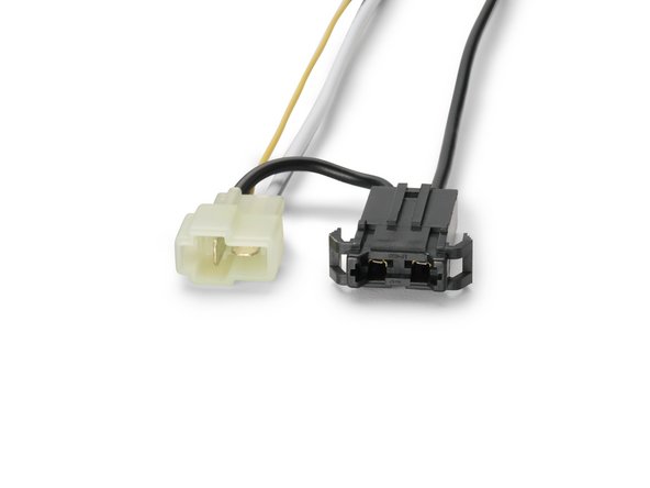
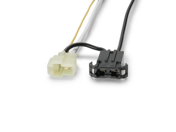
Connect the White 2-pin Molex connector from the Fuse Interrupter to the White 2-pin Molex connector on the HRN-SIFUSETAP harness.
-
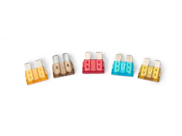
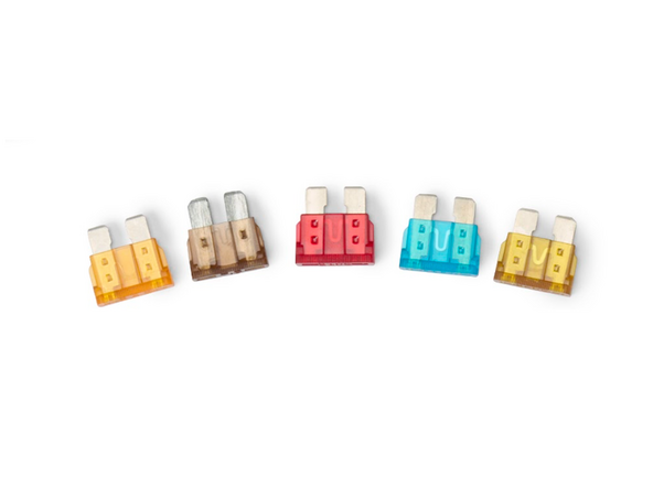
Using the supplied fuses, insert a fuse of the same rating as the one that was removed from the vehicle into the Black Fuse holder on the HRN-SIFUSETAP harness.
-
Ensure the connection is secure.
-
-
-
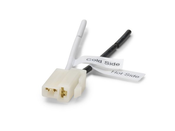
The supplied flying lead harness in the HRN-SIFUSETAP harness kit may be used instead of the Fuse Interrupters to interrupt the starter circuit.
-
Using a digital multimeter, locate the START (cranking) wire — the wire that is at 12V / 24V when the key is in the start position.
-
It is highly recommended to refer to vehicle wire interface diagrams for starter control (i.e. ALLDATA™, WireSheet™, Mitchell1 ProDemand™ / eAutoRepair™ or equivalent) to locate the starter wire in the vehicle.
-
Cut the starter wire.
-
Connect the Black wire (HOT SIDE) to the +12V/24V signal and the White wire (COLD SIDE) to the starter.
-
For all connections, strip 1/2" (15 mm) of insulation, solder, and insulate the connection using heat shrink or electrical tape. Ensure the connections are secure.
-
Connect the White 2-pin Molex connector from the Fuse Interrupter to the White 2-pin Molex connector on the HRN-SIFUSETAP harness.
-
Using the supplied fuses, insert a fuse of the same rating as the starter circuit of the vehicle into the Black Fuse holder on the HRN-SIFUSETAP harness.
-
-
-
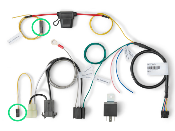
If the HOT side of the Fuse Interrupter is on a switched ignition source, proceed to connect the Black molex connector (Yellow wire) from the HRN-SIFUSETAP harness to the Black molex connector from the Fuse Interrupter connection point (2-pin white molex connector).
-
If the HOT side of the Fuse Interrupter is on a constant +12V/24V source then proceed to the next step.
-
Ensure the connection is secure.
-
-
-
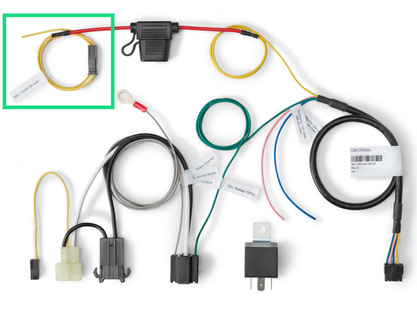
Use the Yellow Ignition pigtail provided with the HRN-SIFUSETAP harness kit to find a true Ignition source +12V / +24V.
-
This ignition source is used to energize the relay.
-
The Ignition source should have +12V / +24V when the Ignition switch is in the ON/RUN and Start positions and should have 0V when the Ignition switch is in ACC or OFF positions.
-
IMPORTANT: Do not connect the yellow wire to a constant power source nor to the vehicle's battery. This can result in the relay constantly draining the vehicle's battery.
-
A Fuse adapter may be used to connect to a location in the fuse panel for the ignition source.
-
The fuse adapter must be supplied by the installer / technician.
-
Use a Digital Multimeter to verify before making the connection.
-
Ensure the connection is secure.
-
-
-
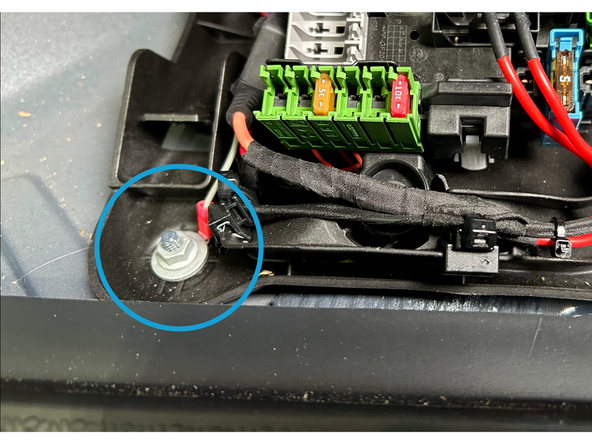
Locate a suitable chassis-ground point.
-
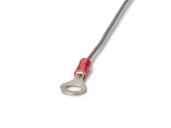
Connect the ring terminal from the HRN-SIFUSETAP harness to the chassis ground.
-
A self-tapping screw can be used to secure the ring terminal to a part of the metal dash frame.
-
IMPORTANT: Ensure there is no wiring or objects behind the location of the ring terminal prior to drilling.
-
Ensure the connection is secure.
-
-
-
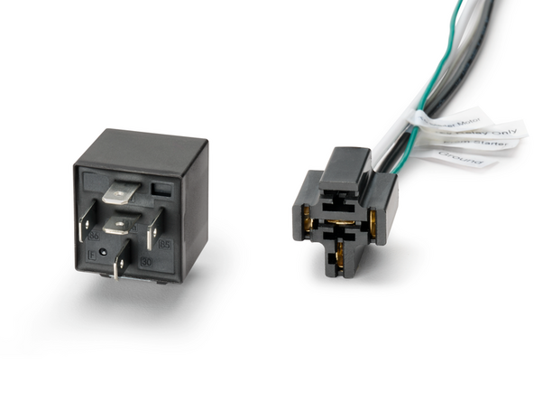
Plug the supplied relay into the 5-pin relay socket.
-
-
-
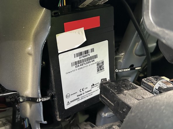
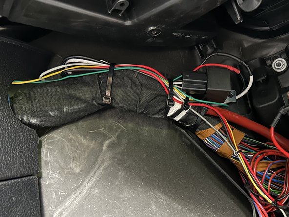
Route the HRN-SIFUSETAP harness to the mounting location of the IOX-KEYLESS
-
It's important to avoid any pinch points and sharp corners when running wires.
-
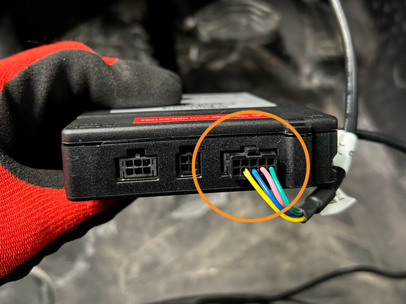
Connect the 10-pin Black Molex Connector from the HRN-SIFUSETAP harness to the IOX-KEYLESS.
-
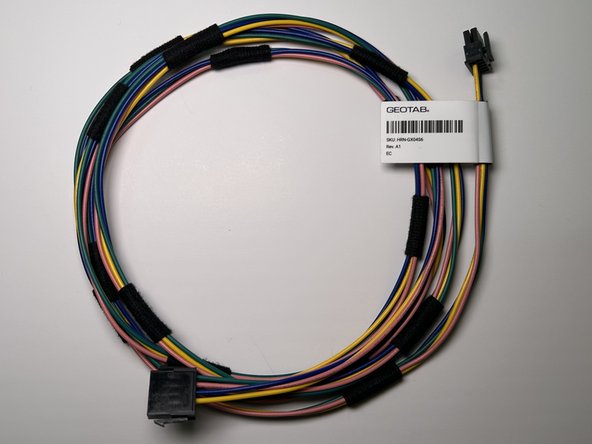
The HRN-GX04S6 harness may be used to extend the HRN-SIFUSETAP harness if additional length is needed to reach the mounting location of the IOX-KEYLESS.
-
Ensure the connection is secure.
-
-
-
Secure excess harness as needed with cable ties
-
Ensure the harness does not interfere with any moving parts or safe operation of the vehicle.
-
Trim any excess cable tie
-
-
-
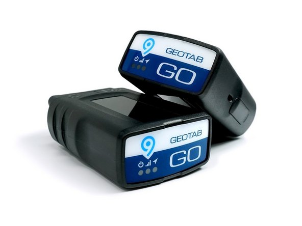
Connect the IOX-KEYLESS to the GO device.
-
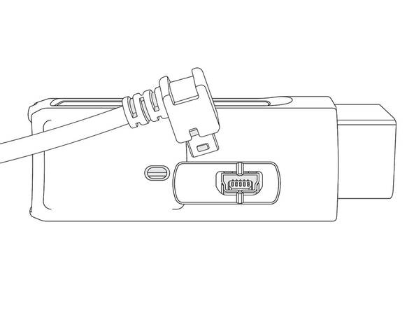
Remove the expansion port cover and plug in the 90° USB connector from the IOX-OUTPUTM into the GO device.
-
Secure the connection with a cable tie.
-
Ensure the cable tie is firmly situated in the grooves, both on the plug and the GO device, to prevent tampering.
-
DO NOT OVER-TIGHTEN! The connector on the device can be damaged if over-tightened.
-
Trim any excess cable tie.
-
-
-
Installations for the IOX-KEYLESS SID (Starter Interrupt Device) solution require a GO device and a T-harness. Refer to the HRN-GS16K2-LD Standard LD 16-Pin T-Harness Kit guide for installation instructions.
-
-
-
All in-vehicle devices and related cabling must be securely fastened and kept clear of all vehicle controls, airbags, and gas, brake and clutch pedals.
-
This requires the use of a cable tie when securing the device or any extension harness to the OBD connector, securing both sides of the harness. If you do not use a cable tie, vibration in the vehicle can lead to a loose connection which could cause the vehicle’s engine computer to fail, causing potential loss of vehicle control and serious injury.
-
Inspect devices and cabling regularly to ensure all devices and cabling continue to be securely attached.
-
If at any point after an in-vehicle device is installed a warning light illuminates on the vehicle dash or the vehicle stalls or has a marked drop in performance, shut off the engine, remove the device, and contact your reseller. Continuing to operate a vehicle with these symptoms can cause loss of vehicle control, and serious injury.
-
-
-
Navigate to one of the following:
-
-
-
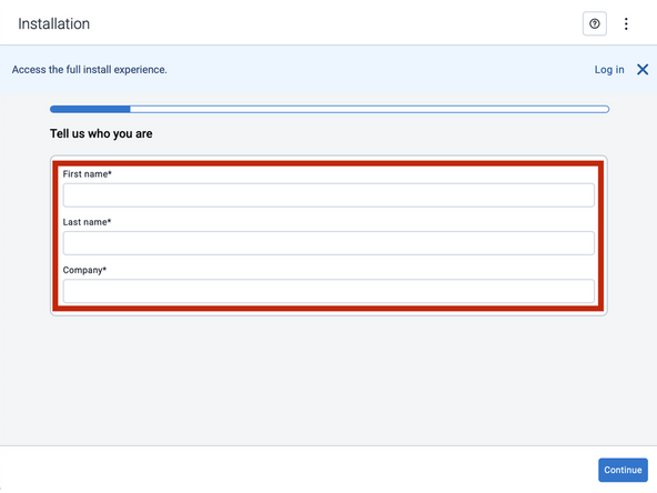
Note that the following steps are for the public version of MyInstall.
-
If you have an installer MyAdmin account, use this link
-
This link is also accessible via the MyInstall Public page.
-
-
-
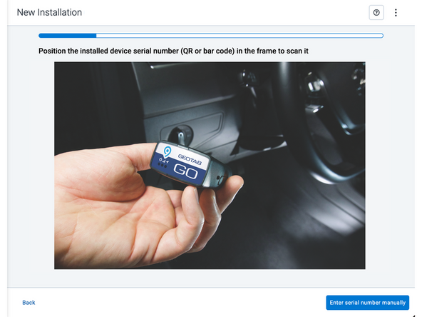
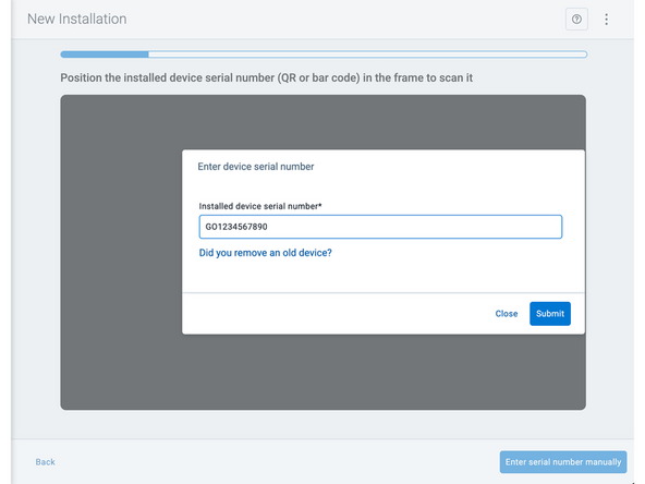
Two options are available to enter the device serial number:
-
Scan the device serial number (QR or barcode) using your mobile device.
-
Press Enter serial number manually, enter the serial number, and then press Submit.
-
If you are also removing an old device, press Did you remove an old device? and then enter the removed device serial number.
-
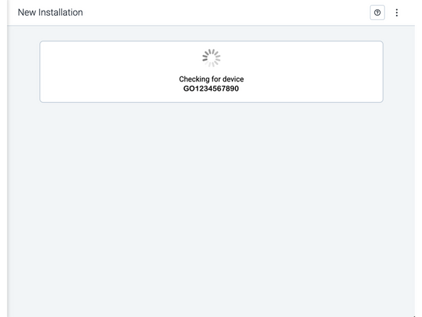
MyInstall takes a moment to check the device status.
-
-
-
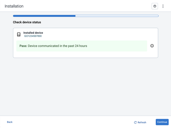
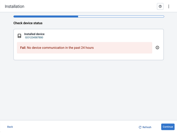
Installed device
-
Pass – The device has successfully communicated with the network in the last 24 hours.
-
Fail – The device has not communicated with the network in the last 24 hours.
-
If the device status shows as FAILED, verify the LED status and turn the ignition / engine off and on again.
-
Press Refresh to check the status again.
-
Refer to the MyInstall User Guide for detailed instructions.
-
-
-
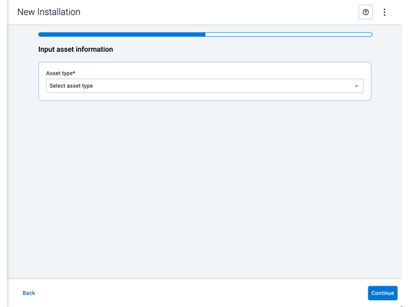
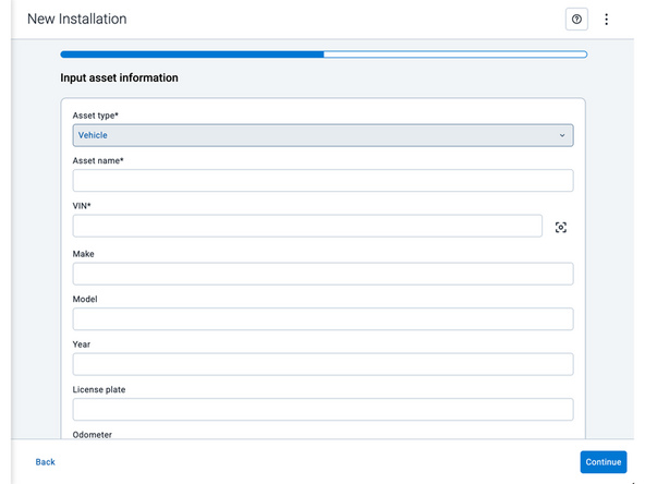
Asset name — Enter the vehicle or asset name. This field is mandatory.
-
VIN — Scan or enter the vehicle identification number (VIN). For scanning, select the scan icon [O] beside the field. This field is mandatory.
-
Make, Model, and Year — This information will be auto populated when you scan or enter a valid VIN. If it is not autopopulated, enter the information manually. NOTE: For some vehicle makes and models, the autopopulate option might not be possible.
-
License plate — Enter the vehicle license plate.
-
Odometer — Enter the vehicle odometer, and select the measurement unit (km or miles).
-
Engine hours — Enter the vehicle engine hours.
-
Camera ID (GO device only) — Scan or enter the installed camera identification (ID) number. NOTE: Depending on the camera type, the camera ID number can also be the camera’s International Mobile Equipment Identity (IMEI), or serial number. Select the information icon ⓘ to learn more about your camera’s ID number.
-
Work order reference — If applicable, enter a work reference number that is associated with the installation.
-
-
-
For the latest version of the Limitations of Use
-
Your in-vehicle devices must be kept clear of debris, water and other environmental contaminants. Failure to do so may result in units malfunctioning or short-circuiting, which can lead to a fire hazard and cause loss or serious injury.
-
This product does not contain any user-serviceable parts. Configuration, servicing, and repairs must only be made by an authorized reseller or installer. Unauthorized servicing of these products will void your product warranty.
-
The simplified EU declaration of conformity referred to in Article 10(9) shall be provided as follows:
-
Hereby, Geotab (Address: 2440 Winston Park Drive, Oakville, Ontario L6H 7V2, Canada, Phone number: 1 (877) 436-8221) declares that the radio equipment type ‘telematics device’ is in compliance with Directive 2014/53/EU. The full text of the EU declaration of conformity is available here.
-
WARNING: Cancer and Reproductive Harm
-



Team
