
Recommended Tools & Consumables
Hardware & Accessories
-
-
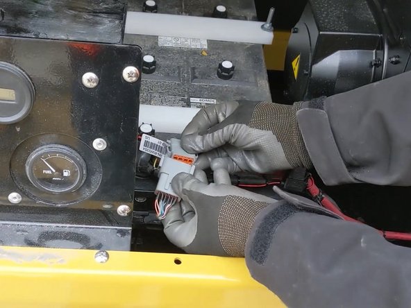
There are 3 wires which must be connected.
-
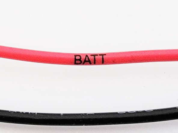
Red
-
+12/24V Constant power must be connected to a true battery source (live at all times).
-
Black
-
Must be connected to a verified ground.
-
Yellow
-
Ignition sense wire must be connected to a true ignition source.
-
+12/24V when the key is in both ON and Run positions, 0 when in Off position.
-
-
-
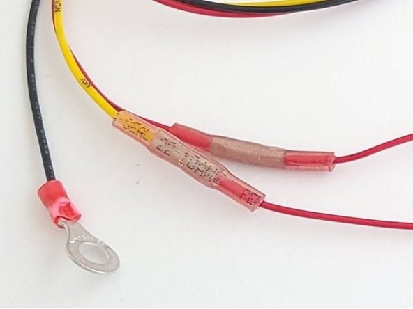
Using your wire crimpers, attach the fuse holders on to the Red and Yellow wires using the included parts.
-
The wires should come with the insulation pre stripped; ready for crimp on connectors.
-
Crimp one of the included butt splice connectors on to the end of the Yellow wire.
-
Crimp the open end from the previous step onto one end of the Fuse holder.
-
Using a heat gun, or other heat source, heat shrink the butt splice connectors.
-
Repeat the above steps for the Red wire.
-
The remaining blunt cut end from the fuse holder will be what is connected to the vehicle.
-
-
-
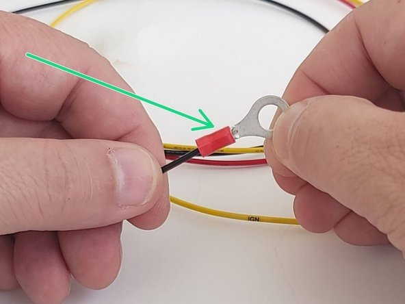
Using your wire crimpers, crimp the ring terminal on to the Black wire.
-
-
-
Geotab does not recommend terminating to unknown circuits! Appropriate reference information is highly encouraged.
-
Known and publicly available publishers for automotive electrical & electronics: Fortin's Wire Color, Alldata DIY, Mitchell 1 DIY.
-
-
-
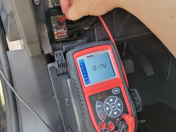
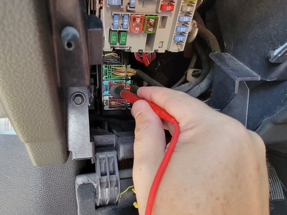
Locate and verify a constant +12/24V Battery source.
-
Always use a Digital Multi Meter.
-
A suitable battery source will have +12/24V at all times, just like if you were to be connected directly to the battery.
-
Typical locations
-
Ignition switch.
-
Fuse and power distribution panels.
-
-
-
Locate and verify a +12/24V Ignition source.
-
Always use a Digital Multi Meter.
-
A suitable Ignition source will have +12/24V while the vehicle's key or button is set to on/run and 0V when set to off.
-
Typical locations
-
Ignition switch.
-
Fuse and power distribution panels.
-
-
-
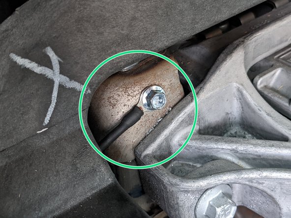
Connect the ring terminal to a verified ground using a self tapping screw (not included) or existing bolt.
-
The surface may need to be prepared prior to connection.
-
The ground surface should be bare metal.
-
Remove any paint, corrosion, or other coating if present.
-
Most heavy structure in the dash area is suitable to use as a ground. Always test using a DMM.
-
Star washers and serrated head screws are recommended. (not included)
-


Team

Authors: Field Service Install Member of Authors: Field Service Install
2 Members
10 Guides authored