Recommended Tools & Consumables
Hardware & Accessories
-
-
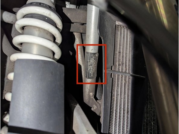
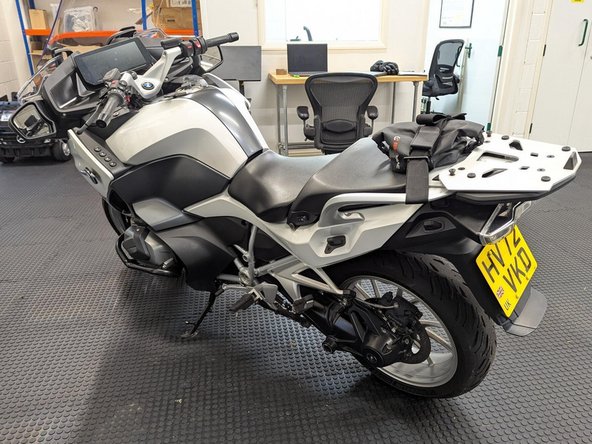
Note the VIN number on the build plate which is located on the front right side of the frame below the steering head.
-
-
-
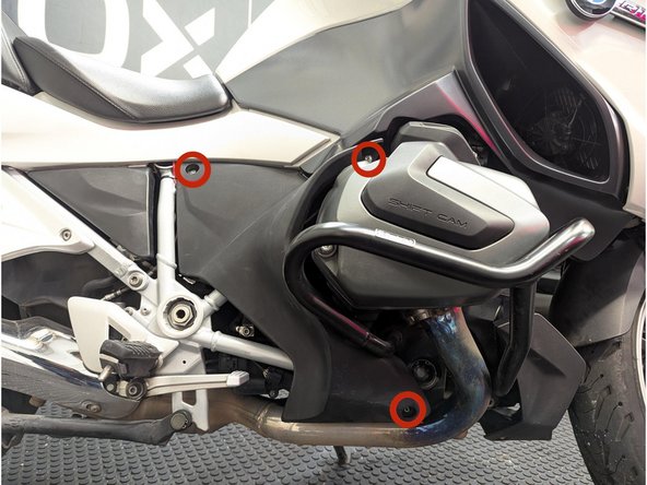
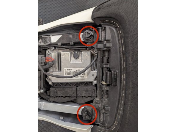
Remove the 3 x T25 screws using a screwdriver.
-
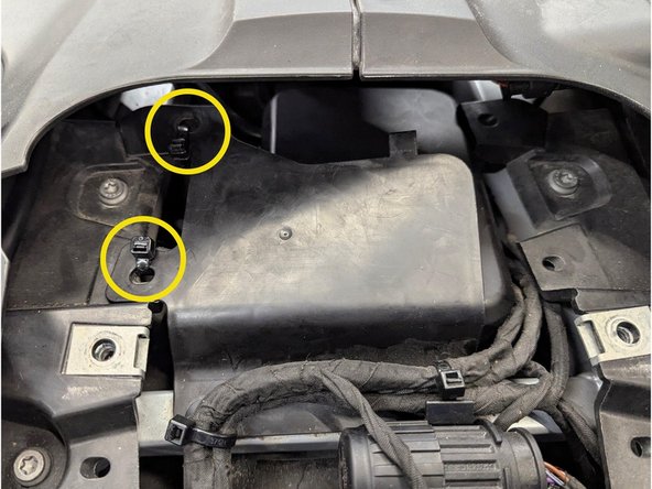
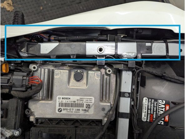
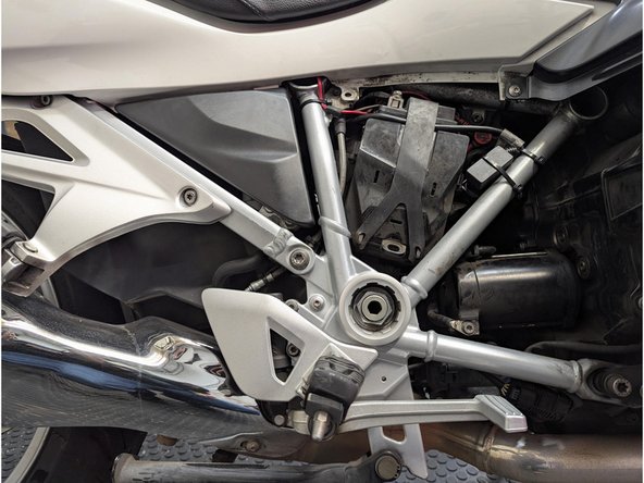
For better access when routing the harness, also remove the spring-strut cover from grommets.
-
-
-
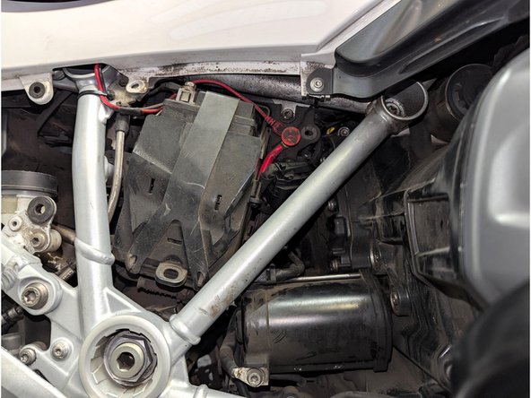
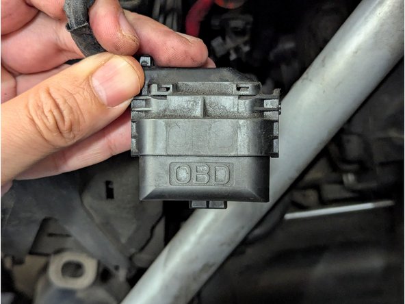
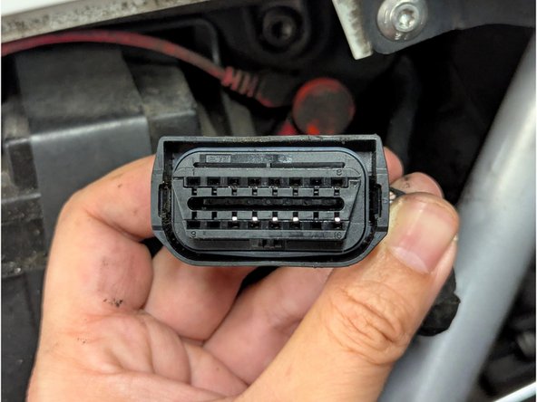
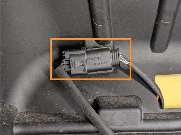
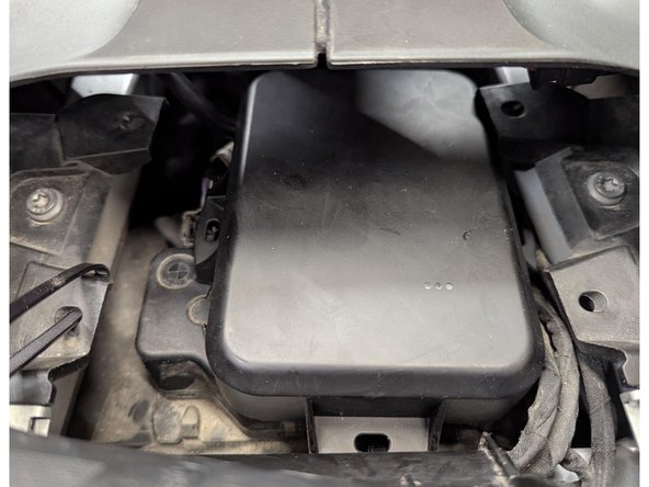
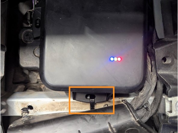
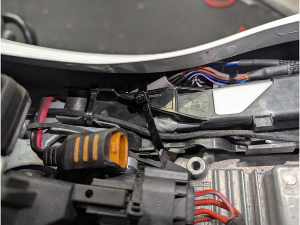
Locate the diagnostic connector and remove the protective cap.
-
-
-
Unlock the seat by turning the ignition key clockwise and then slightly raise the seat at the back.
-
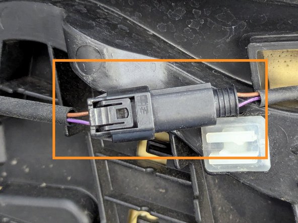
Disconnect the 2-pin connector for the heated seat.
-
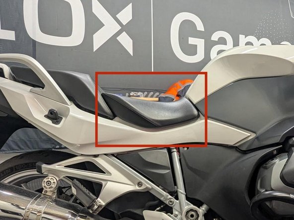
The toolkit can be found at the back of the rider seat as well.
-
-
-
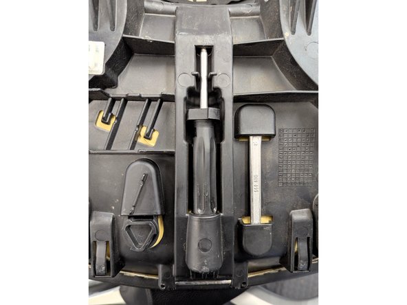
Remove the 2 screws using the appropriate tool from the onboard toolkit.
-
Pull the passenger seat slightly forward and lift the seat slightly.
-
Disconnect the 4-pin connector for the heated seat and remove the passenger seat.
-
-
-
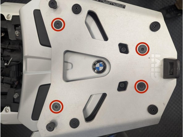
Remove the 4 x Hex screws using a screwdriver.
-
-
-
Remove the 2 x T20 Torx screws using a screwdriver.
-
-
-
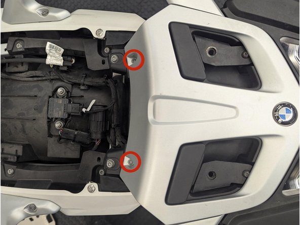
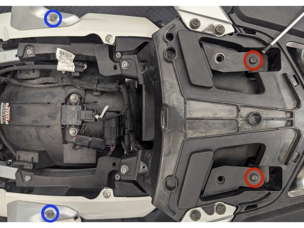
Remove the 2 x T25 Torx screws.
-
Remove the 2 x Hex screws.
-
Remove the grab handles and set aside.
-
-
-
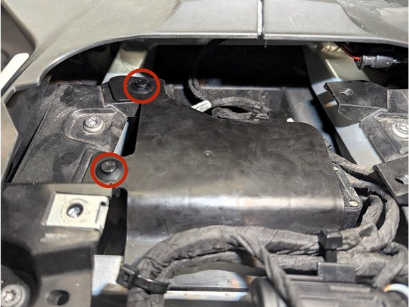
Remove the 2 x expanding rivets using a flat screwdriver or an appropriate removal tool then pull the cover outwards.
-
-
-
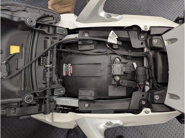
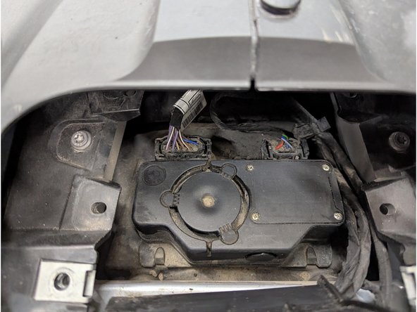
Wipe clean the surface area of the control unit.
-
Apply 3M Heavy Duty double sided mounting tape to the back of the GO9 RUGGED.
-
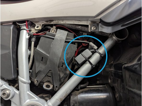
Mount the GO9 RUGGED on top of the control unit as shown.
-
Press firmly to ensure proper adhesion.
-
Use additional cable ties to further secure the GO9 RUGGED.
-
Replace back the control unit cover. You may use cable ties to hold it in place as shown.
-
Trim any excess cable tie
-
-
-
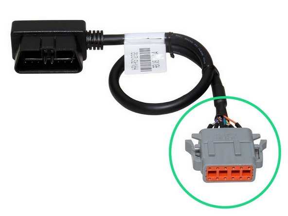
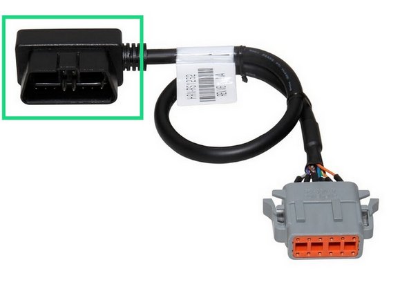
Connect the HRN-RS12S2 harness to the GO9 RUGGED connector.
-
Ensure the connection is secure and locked into place.
-
Route the other end of the HRN-RS12S2 harness to the diagnostic port location.
-
Secure excess wiring with cable ties as needed.
-
Trim any excess cable tie.
-