Recommended Tools & Consumables
Hardware & Accessories
-
-
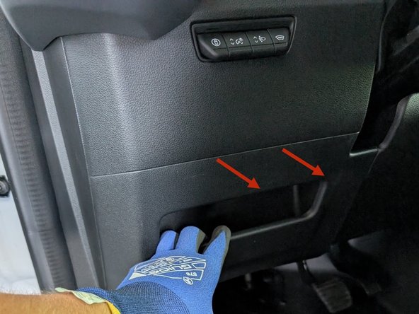
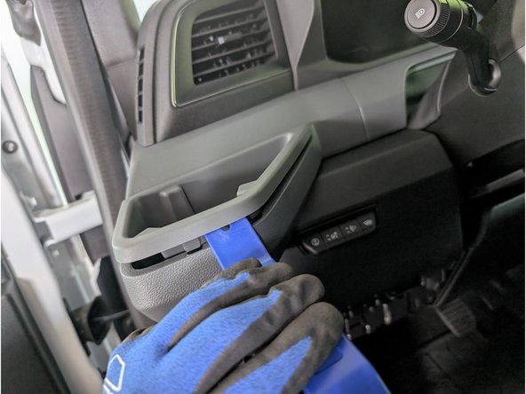
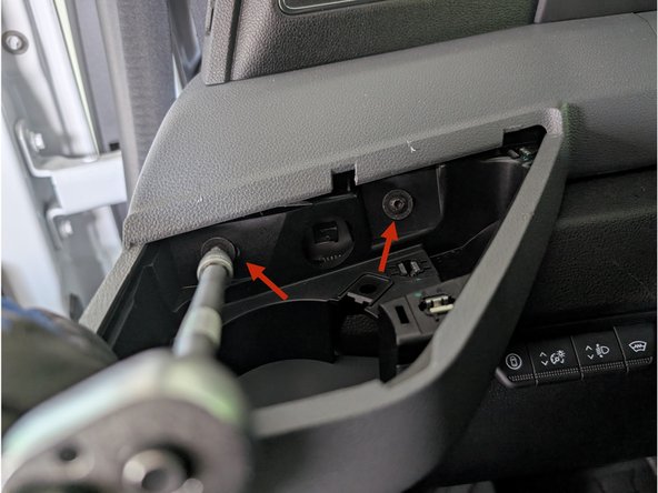
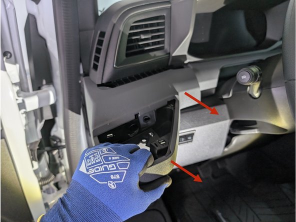
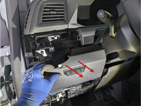
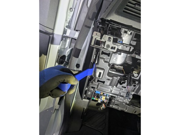
Pull the panel and remove the cover from the fuse-box carefully.
-
-
-
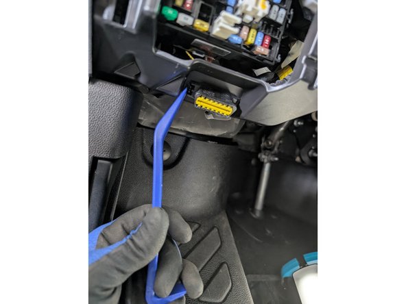
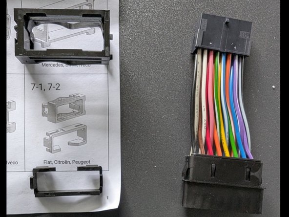
Use the adaptors 7 and 7.2 to mount our T harness appropriately at the origin of the OBD port.
-
There is an example of how to lock adapter 7.2 into adapter 7.
-
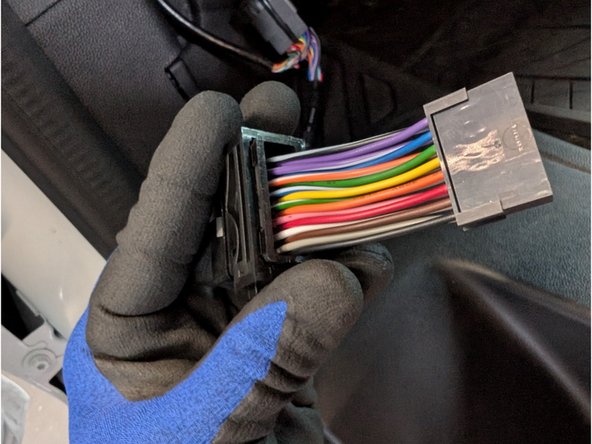
Insert the adapter number 7 into the OBD bracket. Push the harness with the molex connector end through the front of the Adapter, until it locks. Install the adapter 7.2 into the adapter 7 to lock it.
-
-
-
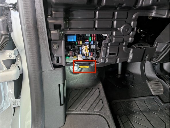
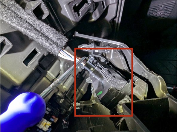
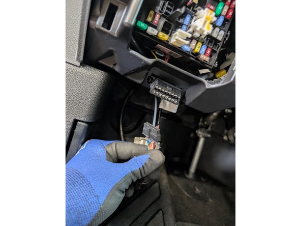
Plug the female connector from the T-harness into the OEM OBDII connector.
-
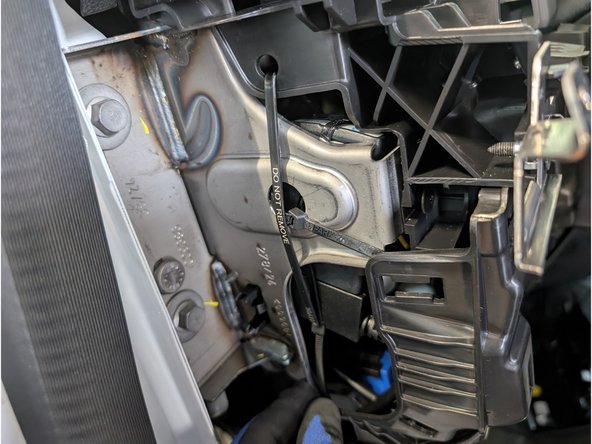
Secure connection with a cable tie.
-
Trim excess cable tie flush!
-
-
-
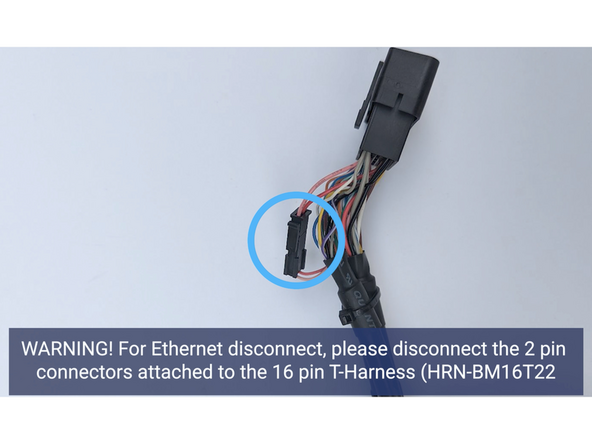
! IMPORTANT: For Ethernet bypass (pins 3 & 11), disconnect the 2-pin Molex connector. This applies to select vehicles, refer to this link for the applicable vehicle list.
-
-
-
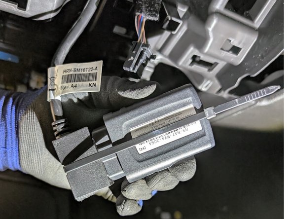
Plug the GO device into remaining end of the harness.
-
Secure the device to the harness with included cable tie.
-
Trim excess cable tie flush!
-
Every device has a black serialized cable tie included & should be used in this step.
-
-
-
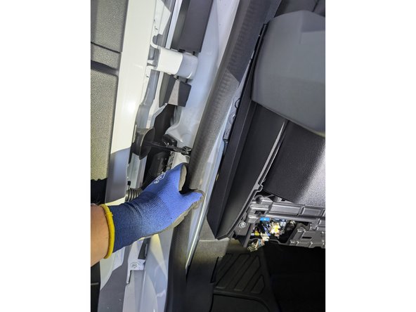
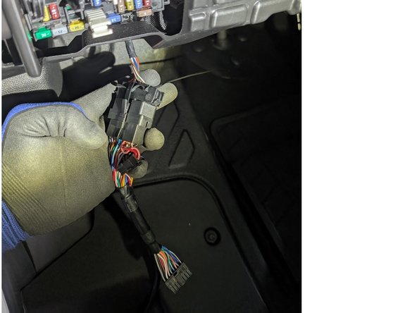
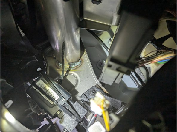
Route device and harness to mounting location as needed.
-
Ensure cable does not interfere with any moving parts & secure harness as needed with cable ties.
-
Secure device using cable ties.
-
Point to secure device using cable tie.
-
To ensure reporting quality the device must be secured with no free movement!
-
Device must not be secured with bottom side facing in direct contact of metal!
-